:CRECovery:LSELect
Command Syntax
:CRECovery:LSELect {LOOP1 | LOOP2 | LOOP3 | LOOP4}
Query Syntax
:CRECovery:LSELect?
Description
This command selects the Type-2 loop transition frequency (peaking) in the JTF Receiver's clock recovery. In normal operation, the Type-2 transition frequency is automatically coupled to the clock data recovery's loop bandwidth and provides the desired loop characteristic for most measurements. Use :CRECovery:LSELect:AUTomatic child command to turn off automatic coupling.
- LOOP1
- Selects 12 kHz (available for all loop bandwidths).
- LOOP2
- Selects 280 kHz (available for loop bandwidths > 600 kHz).
- LOOP3
- Selects 640 kHz (available for loop bandwidths > 1.6 MHz).
- LOOP4
- Selects 1.3 MHz (available for loop bandwidths > 4.5 MHz).
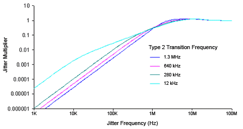
Clock recovery extracts a clock from the incoming signal and provides the DCA-X with a trigger that is synchronous with the data. The clock recovery loop bandwidth primarily determines how well the recovered clock tracks low-frequency jitter on the input signal. Some signals have very large low-frequency jitter from either extremely dirty clocks or intentional modulated clocks such as found in SSC (spread spectrum clocking). In this case, modules like the N1060A clock recovery system provides additional control of the loop dynamics by allowing the user to select the Type-2 transition frequency of the loop. The Type-2 transition frequency indicates the frequency below which the second integrator in the loop starts to provide extra gain. Increasing this frequency provides additional loop gain and improves the tracking of the loop. The following figure shows the jitter multiplier as a function of jitter frequency for a loop-bandwidth setting of 5 MHz and various settings of transition frequency. This multiplier is the magnitude of the observed jitter transfer function (OJTF). This additional tracking also increases the peaking in the closed-loop jitter transfer function (JTF).
Figure. OJTF for 5 MHz LBW vs. Type-2 Transition Frequency

How do you identify the module's slot number location?
- In FlexDCA, the slot number is added to the subsystem name. For example,
:CRECovery2:CRATe. - In FlexPLL, the slot number is specified using the
:RDCA:CRECovery:SLOTcommand. The slot number is not used in the command. For example,:CRECovery:CRATe. From the GUI, enter the slot number in the DCA CDR Location field of the Receiver Setup dialog.
For FlexPLL application, requires revision A.06.70 and above.