Making a Custom OFDM Measurement Using legacy Resource Interface = Type1 associated API properties
This topic is currently only applicable when using the Resource Interface = Type1 legacy API 1) Access Preamble Indicator, or 2) Application Programming Interface property set.
Please note, use of the newer Frame Definition API properties are strongly recommended when creating any new Custom OFDM Orthogonal Frequency Division Multiplexing: OFDM employs multiple overlapping radio frequency carriers, each operating at a carefully chosen frequency that is Orthogonal to the others, to produce a transmission scheme that supports higher bit rates due to parallel channel operation. OFDM is an alternative tranmission scheme to DSSS and FHSS. measurement setup configurations for improved usability.
Upon selecting Frame Definition Apply, any new Custom OFDM measurement setup configurations will be applied using the new Resource Interface Type2 associated set of API properties.
This topic describes how to configure the VSA to make a Custom OFDM measurement including instructions to create OFDM Phy Layer signal description setup files necessary to configure the demodulator to analyze custom, or non-standard, OFDM signals.
Overview
You must manually configure the VSA Custom OFDM demodulator to measure your signal. The process to configure the VSA Custom OFDM demodulator consists of three steps:
- Specify the high-level PHY Physical Layer Layer and FFT Fast Fourier Transform: A mathematical operation performed on a time-domain signal to yield the individual spectral components that constitute the signal. See Spectrum. parameters for the OFDM signal under test;
- Describe the detailed signal frame structure in the form of 4 configuration files that define each subcarrier in each symbol.
- Configure the measurement setup parameters, e.g. synchronization type, result length, etc.
Signal Setup
Before selecting the Custom OFDM demodulation mode, make sure that the input signal is correctly captured by the analyzer. Specify the VSA basic signal measurement setup parameters so that the input signal is fully captured including; the center frequency, span, input range, etc.. You can use the Spectrum and Time traces to verify that the signal of interest is properly captured.
Tutorial Demo Signal
This measurement tutorial uses a demo signal based on an 802.11a/g OFDM signal. The Custom OFDM configuration developed below can be used with the supplied VSA Demo Signal "CustomOFDM_80211a" which uses the "CustomOFDM_80211a.sdf" recorded signal.
To use the demo signal, recall the "CustomOFDM_80211a" Demo Signal, click navigate to the "%PROGRAMFILES%\Keysight\89600 Software <ReleaseVersion>\89600 VSA Software\Help\Signals\Custom OFDM" folder and click the "" Demo Signal File.
Configuring the Demodulator
Step 1 - Specify the signal symbol FFT parameters
To begin, select the Custom OFDM demodulator, click . Then open the Custom OFDM Demod Properties dialog, click .
Loading the "" Demo Signal File will auto-select the Custom OFDM demodulator.
Select the Demod Properties tab and specify the following five FFT parameters: FFT Length, Guard Interval, Guard Lower Subcarriers, Guard Upper Subcarriers, and OFDM System Sample Frequency.
The PHY Layer parameters are typically located in the early part of the technical standard.
These particular OFDM setup parameter values are specific to the "CustomOFDM_80211a.sdf" signal under test.
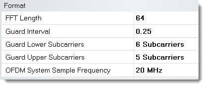
- The FFT Length can be specified in any even incremental value between 4 and 65536.
- The Guard Interval is usually between 1/16 and 1/4, and is entered in decimal notation.
- The number of active subcarriers is generally fewer than 2N, with empty guard subcarriers allocated on either side of the signal.
- The number of active subcarriers is usually odd, due to the null subcarrier (subcarrier 0) in the center, and equal quantities on either side. This results in an odd number of guard subcarriers. Most standards define the lower guard region with one more subcarrier than the upper.
Step 2 - Define the Detailed OFDM Preamble and Payload Symbol Data
Because this is a non-standard custom OFDM signal, the OFDM signal frame structure, preamble and data symbols must be described in detail so that the VSA can correctly demodulate the signal. The VSA uses the following 4 OFDM configuration text files to define the OFDM symbol data:
| OFDM Signal Configuration File | Description |
|---|---|
| Resource Map file | The Resource Map file The Resource Map file defines the function of each subcarrier in each symbol, describing whether it is a preamble, pilot, data or null subcarrier. defines the function of each subcarrier in each symbol, describing whether it is a preamble, pilot, data or null subcarrier. |
| Resource Modulation file | The Resource Modulation file The Resource Modulation file specifies the modulation format expected for each subcarrier defined in the Resource Map. specifies the modulation format expected for each subcarrier defined in the Resource Map. |
| Preamble I-Q file | The Preamble I-Q file The Preamble I-Q file defines the expected I and Q values for each preamble subcarrier. defines the expected I and Q values for each preamble subcarrier. |
| Pilot I-Q file | The Pilot I-Q file The Pilot I-Q file defines the expected I and Q values for each pilot subcarrier. defines the expected I and Q values for each pilot subcarrier. |
The OFDM Signal configuration files are all simple text files consisting of numeric values separated by spaces, commas, tabs, or CR/LF. The file extension may be .txt or .csv. For clarity, it may be useful to organize these files with one row of values per symbol, but this is entirely optional.
Resource Map File
The Resource Map file defines the function of each subcarrier in each symbol, describing whether the subcarrier is a preamble, pilot, data, or null subcarrier type. The Resource Map file must contain one value for each active (i.e. non-guard) subcarrier, including the "DC" center subcarrier. Thus, the map for an 802.11a/g signal (FFT size of 64 with 11 guard subcarriers) will contain 53 values per symbol.
| Resource Type Resurce Type specifies the function of the measurement subcarriers; preamble, pilot, data, All, UserN, Unknown, or Null subcarrier | Resource Type |
|---|---|
| 0 | Data subcarrier |
| 1 | Pilot subcarrier; known |
| 2 | Pilot subcarrier: unknown (see "Pilot I-Q File") |
| 3 | Preamble subcarrier |
| 4 | null subcarrier |
| 5 | Unspecified |
The Resource Type may have values as high as 1023 per symbol depending on the FFT size. For certain advanced configurations (described later in this note), the Resource Type is treated as a 10-bit number, with the higher-level bits used to indicate items such as user number, MIMO Multiple Input, Multiple Output: A physical layer (PHY) configuration in which both transmitter and receiver use multiple antennas. antenna number, etc.: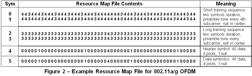
If the number of pilots in the pilot values array is insufficient to populate the resource map, the pilots values are repeated to fill the remaining resource map pilot locations.
Resource Repeat Index:
The resource map for most OFDM signals will consist of one or more preamble symbols, sometimes followed by specialized header symbols, followed by a repeating pattern of similarly-formatted symbols. For these repeating symbols, it is only necessary to define the pattern once; the Resource Repeat Index The resource map for most OFDM signals will consist of one or more preamble symbols, sometimes followed by specialized header symbols, followed by a repeating pattern of similarly-formatted symbols. For these repeating symbols, it is only necessary to define the pattern once; the Resource Repeat Index tells the analyzer how to loop when the end of the Resource Map file is reached. tells the analyzer how to loop when the end of the Resource Map file is reached.
In the preceding Example Resource Map File for 802.11a/g OFDM, the Resource Repeat Index is 5, meaning that the 5th symbol (starting count from zero) is to be repeated indefinitely. If the index was 4, the 4th and 5th symbols would be repeated in sequence, and so on.

Resource Modulation File
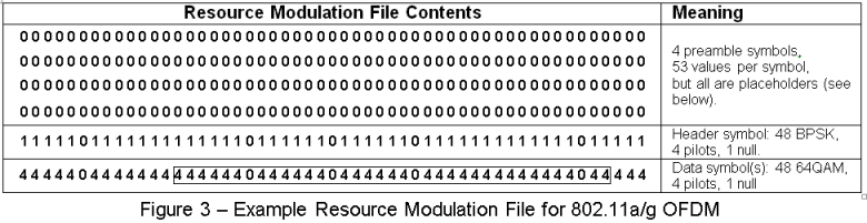
The Resource Modulation file specifies the modulation format expected for each subcarrier defined in the Resource Map. The Resource Modulation file contains one Resource Modulation value for every subcarrier defined in the Resource Map file. The Resource Modulation value does not directly specify the modulation format. The Resource Modulation is an index that references a QAM Quadrature Amplitude Modulation Identifier value that is also in index that references a QAM Level value that specifies the subcarrier QAM Level (for example 4QAM, 8QAM, 16QAM... etc.).
The QAM Identifiers parameter:
The QAM Identifiers The QAM Identifiers parameter is specified in the Format tab > QAM Idenifiers text box (Custom OFDM Demod Properties dialog box). parameter is specified in the Format tab > QAM Idenifiers text box (Custom OFDM Demod Properties dialog box).

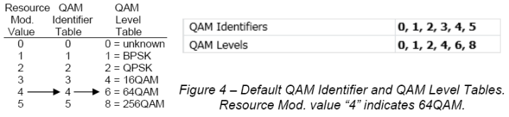
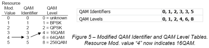
As previously mentioned, the Resource Modulation file does not define the modulation type directly. Rather, the Resource Modulation is an index into the QAM Identifier table, which provides an index into the QAM Level table. Both of these parameter tables are specified on the Format tab of Custom OFDM Demod Properties dialog box. In the example below (fig. 4), a Resource Modulation value of 4 points to the 4th value (counting from zero) in the QAM Identifier table, which is also 4. These values result in a specified modulation format of 64QAM as follows; A QAM Identifier equal to 4 points to the 4th value in the QAM Level table which is 6 that specifies a 64QAM modulation format.
The advantage to this scheme is that subcarrier modulation definitions can be changed quickly and easily without modifying the Resource Modulation file. Figure 5 shows how all subcarriers defined as 64QAM can be changed to 16QAM by simply modifying a single value in the QAM Identifier table (change from a 4 to a 3). In this example, the Resource Mod value of 4 is not changed and continues to point to the 4th value in the QAM Identifier table. However, the resulting index into the QAM Level table has changed to 3 which points to the third value in the QAM level table which is 4 specifying 16QAM.
The Custom OFDM demodulator supports the following QAM Levels:
| QAM Levels | Modulation | Comments |
|---|---|---|
| 0 | Unknown | Modulation auto-detection mode. |
| 1 | BPSK Binary phase shift keying - A type of phase modulation using 2 distinct carrier phases to signal ones and zeros. | |
| 2 | QPSK Quadrature phase shift keying | |
| 3 | 8 PSK Phase Shift Keying: A broad classification of modulation techniques where the information to be transmitted is contained in the phase of the carrier wave. | |
| 4 | 16 QAM | |
| 5 | 32 QAM | |
| 6 | 64 QAM | |
| 7 | 128 QAM | |
| 8 | 256 QAM | |
| 9 | 512 QAM | Does not support modulation auto-detection mode (zero "Unknown"). |
| 10 | 1024 QAM | Does not support modulation auto-detection mode (zero "Unknown"). |
| 11 | 2048 QAM | Does not support modulation auto-detection mode (zero "Unknown"). |
| 12 | 4096 QAM | Does not support modulation auto-detection mode (zero "Unknown"). |
| 13 | 8192 QAM | Does not support modulation auto-detection mode (zero "Unknown"). |
| 14 | 16384 QAM | Does not support modulation auto-detection mode (zero "Unknown"). |
| 15 | 32768 QAM | Does not support modulation auto-detection mode (zero "Unknown"). |
| 16 | 65536 QAM | Does not support modulation auto-detection mode (zero "Unknown"). |
| n/a | 8 QAM | no QAM Levels value, must use auto-detection mode (0-unknown) |
| n/a | Rotated BPSK/QPSK | no QAM Levels value, must use auto-detection mode (0-unknown) |
Auto-detecting the modulation format:
Resource Modulation value zero “unknown” is a special case that can greatly simplify Custom OFDM setup. Resource Modulation zero instructs the demodulator to detect the format automatically based on a statistical algorithm. This algorithm computes a single result (modulation format) for all subcarriers specified as zero. Resource Modulation "zero" is normally used for a group of subcarriers spread across one or more symbols that all utilize the same modulation format.
The auto-detection algorithm does not support any QAM modulation greater than 256QAM. If your signal uses these modulation formats, you must explicitly use QAM levels (9-16) shown in the table above. Auto-detection algorithm does support 8-QAM and rotated versions of BPSK and QPSK. There is no QAM level value corresponding to these formats, so if your signal uses one of these, auto-detection is the only way to demodulate these subcarriers correctly.
Placeholder values:
The Resource Modulation file must always have the same number of values as the Resource Map file. However, not all Resource Modulation values are actually used by the demodulator. This is because some subcarriers have no modulation (Resource Type 4 or 5) and some are defined in separate I-Q files (Resource Types 1 and 3, see next section). The Resource Modulation values provided for these subcarriers will thus be ignored and can be set to any number desired, even numbers assigned to other formats. In the example shown above, zero is used as a placeholder even though it usually means ‘unknown‘ modulation format.
Reference Preamble I-Q File
The Preamble I-Q file defines the expected (reference) I and Q values for each preamble subcarrier. This file contains I and Q values for every preamble subcarrier (Resource Type 3) defined in the Resource Map file. Each time the demodulator encounters a “3” in the Resource Map file, it reads the next two values from the Preamble I-Q file and uses these values as the ideal I-Q location for that preamble subcarrier.
The "I" value is listed first, then the Q value second – do not swap the values!
I-Q values are interpreted as being relative to the average constellation power (i.e. the “constellation reference power”), which is defined as 1.00. A preamble subcarrier boosted by 3 dB would thus have a magnitude of 1.414, e.g. 0+j1.414, 1.00+j1.00, etc.
In most OFDM signals the preamble subcarriers are a constant magnitude and may, or may not, be boosted relative to the constellation reference power. The phase of each preamble subcarrier is usually one of two values (for BPSK) or four values (for QPSK), and typically follows a PRBS Pseudo-Random Binary Sequence sequence defined by the standard. All of this information must be known in order to construct the preamble I-Q file.
The quantity of values in the Preamble I-Q file is equal to twice the total number of preamble subcarriers, summed across all preamble symbols. The Preamble I-Q file contains values only for preamble subcarriers, not data, pilot or null subcarriers.
In the following example, the first I-Q pair is read as 1.47 + j1.47, and refers to the first preamble subcarrier designated by the Resource Map file in Figure 2, i.e. the third subcarrier in the first symbol. Based on these I-Q values, the analyzer expects this preamble subcarrier to have a magnitude of 2.03 and phase of 45 degrees, relative to the constellation reference power.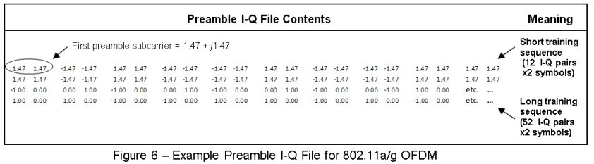
Reference Pilot I-Q File
The Pilot I-Q file provides the ideal (reference) I-Q locations for each known pilot (resource type = 1) shown in the Resource Map file. The quantity of values in this file is thus equal to twice the number of pilots defined in the Resource Map.
Unknown pilots:
in many cases, it will be simpler to define the pilots as "Unknown" (Resource Type = 2), and define only the expected constellation shape (i.e. BPSK) and boosting level. Based on this information, the analyzer will determine the ideal states empirically, and not require a Pilot I-Q file. No knowledge of the Pilot PRBS sequence is therefore required.
Note that "Known" pilots (Resource Type = 1) allow the demodulator to synchronize more reliably under poor SNR Signal-to-Noise Ratio conditions. In addition, the received pilot PRBS sequence is verified against the sequence defined in the Pilot I-Q file so it can detect coding errors in the signal under test.
"Known" pilots can also be used for synchronization, in the case of signals having no preamble. This is not possible with "Unknown"pilots.
In summary, the choice of "Known"versus "Unknown" pilots effects the values specified in the configuration files as follows:\
| Pilot Type | Resource Map Value |
Pilot I_Q File | Resource Modulation File Values |
|---|---|---|---|
| Known | 1 | File required; defines the ideal I-Q states. | Specify either actual modulation format, or “unknown”. |
| Unknown | 2 | File not required. | Specify either actual modulation format, or “unknown” |
1) For BPSK pilots that are rotated to lie entirely on the vertical (Q) axis, always use unknown modulation format, and either: a) unknown pilots; or b) known pilots plus a valid Pilot IQ file.
2) Unknown pilots are assumed to have magnitudes of 1.00 relative to the constellation reference power. If not, a relative boosting factor must be specified on the Format tab.
Reference Pilot I-Q File
The Data I-Q file defines the expected (reference) I and Q values for each data subcarrier. This file contains I and Q values for every data subcarrier (Resource Type 0) defined in the Resource Map file. Each time the demodulator encounters a “0” in the Resource Map file, it reads the next two values from the Data I-Q file and uses these values as the ideal I-Q location for that data subcarrier. Each reference data (refData) in-phase/quadrature (IQ) value of the subcarrier is represented by a complex in-phase/quadrature (IQ) value, real part first, then imaginary part.
Step 3 – Configure the Measurement Parameters
The setup options for the Flexible OFDM demodulator are similar to those provided for the existing 89600 VSA OFDM formats. More complete descriptions can be found in the Custom OFDM Demodulation Properties Dialog Box:
Format Tab
- Format Details: Boosting
- Signal is Bursted (when selected, also set Pulse Search parameters on the Time tab).
- Boosting: by default, the analyzer assumes that all modulation types are scaled the same way, i.e. the average power is 1.00. This section of the setup menu allows separate scaling factors for each modulation type, for each user number (see below) and for unknown pilots.
Time Tab:
- Measurement Interval and Offset
- selects the number of symbols to be displayed.
- Result Length
- selects the number of symbols to be demodulated.
- Result Length selection
- set to “automatic”, the analyzer demodulates only to the end of the current burst.
- Search length
- sets the amount of waveform to acquire per measurement. Typically set to two burst “on” times plus one burst “off” time.
- Pulse search
- selected, the analyzer automatically aligns the measurement with the rising edge of the RF Radio Frequency: A generic term for radio-based technologies, operating between the Low Frequency range (30k Hz) and the Extra High Frequency range (300 GHz). envelope. If not selected, use triggering to position the first symbol near the start of the time record.
Equalizer & Tracking Tab:
- Equalizer use Data/Pilots/Preamble
- use some or all of the subcarriers for Equalizer training. Note: to analyze an OFDM signal that has no preamble, de-select “Use Preamble” in this section, and configure the analyzer for “known” pilots.
- Equalizer averaging mode
- determines whether channel response data, taken across multiple symbols, should be averaged using Equal Weight or Least Squares. Equal Weight averaging is generally more effective at noise reduction, and is recommended unless otherwise required by the standard.
- Track Amplitude/Phase/Timing
- same as current OFDM demodulators.
Advanced Tab:
- Extended Frequency Lock Range
- allows the demodulator to remain locked with a larger center frequency offset, with some tradeoff of noise immunity.
- Synchronization Mode
- use “Time Correlation” for traditional preamble or pilot-based sync; “Cyclic Prefix” may be of value for unknown, missing or poorly-formed prefixes.
Advanced Topics
1. Multi-User OFDM
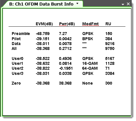
In some forms of OFDM, the physical resource (i.e. the set of subcarriers) is shared among multiple users. The subcarriers for one user may have a different modulation format and/or power level than those for other users making it desirable to view measurement results on a per-user basis.
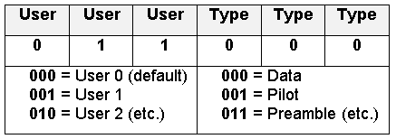
To accomplish this, each subcarrier in the Resource Map can be assigned to an arbitrary User Number between 0 and 7. The User Number and Resource Type are entered into the Resource Map as a single 6-bit number, equal to (User Number x8) + Resource Type.
When programmed for multiple users, the VSA “Data Burst Info” table displays individual results for each user number, as shown in figure 7.
User numbers are valuable even for non-OFDMA signals. For example:
- When using “unknown” modulation format, autodetection is performed separately for each user number, so that several regions can be autodetected independently.
- Constellation reference power (i.e. boosting ratio) can be set separately for each user number, enabling measurements of signals with multiple power levels.
2. MIMO Analysis
The Custom OFDM demodulator can be configured to recover and analyze up to 4 MIMO transmit streams. This is accomplished using the same configuration files described earlier in this note, but with certain modifications.
Configuration details depend on the type of MIMO being analyzed:
| MIMO Type | Characteristics |
|---|---|
| Type 1 (non-overlapping) | Any given pilot or preamble subcarrier is transmitted on only one antenna at a time, and is null on all other antennas. (Examples: WiMAX, LTE) |
| Type 2 (overlapping) | All preamble and pilot subcarriers are transmitted on all antennas at all times. (Example: 802.11n) |
For both types of MIMO, it is assumed that data subcarriers are transmitted simultaneously on all antennas, and have the same modulation format on all antennas.
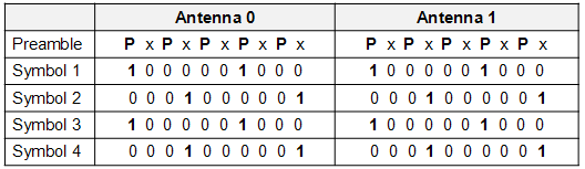
- Configuring Type 1 MIMO: To further illustrate this class of signals, consider the simple MIMO signal shown below.
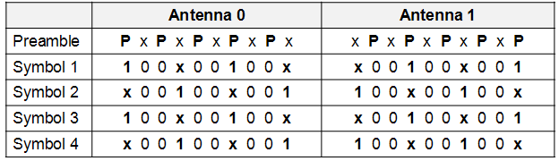
The non-overlapping preamble tones (P) in the first symbol, and the non-overlapping pilot tones (1) in the subsequent symbols. The required configuration file modifications are as follows:
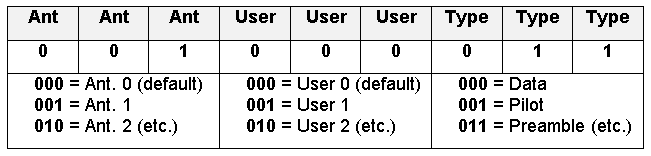
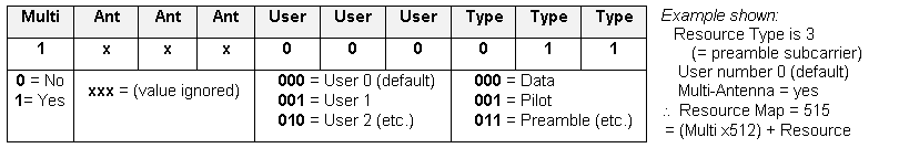
For each preamble or pilot subcarrier, treat the Resource Type value as a 9-bit number, with the upper three bits representing the antenna number. Thus, to assign an antenna number, add (Antenna Number x64) to the Resource Type. When an antenna number is assigned to a resource, that resource is assumed to be active on that antenna only, and null on all other antennas. Antenna number may change from symbol to symbol.
Example Details:
- Resource Type is 3 (= preamble subcarrier)
- User number is 0 (default)
- Antenna number is 1
- Resource Map value = 67 = (Ant No. x64) + Resource
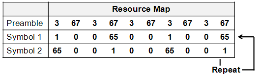
For the simplified MIMO signal shown above, the modified Resource Map would appear as follows – notice how it describes the signals on both antennas at once.
- Resource Modulation file: this file requires no modification; as before, it contains one Resource Modulation value for each subcarrier shown in the Resource Map file.
- Preamble and Pilot IQ files: because these files also describe multiple signals at once, they will generally have more entries than a SISO file. Beyond that, the basic rules still apply: include one I-Q pair, scaled to the constellation reference power, for each preamble or pilot shown on the Resource Map (omitting data, null and guard subcarriers), and enter them in the same sequence as they appear in the Resource Map file.
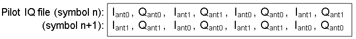
In the simple MIMO Resource Map above, the preamble tones alternate between antenna 0 and antenna 1. In the Preamble I-Q file, the values alternate the same way, i.e.:

The same is true for the Pilot IQ file, where additional lines are needed because the pilot sequence repeats across multiple symbols:
- this class of signals is represented by the following simplified example:
Notice how preamble (P) and pilot (1) subcarriers are over-lapping, i.e. active on both antennas simultaneously. This is handled within the configuration files as shown below.
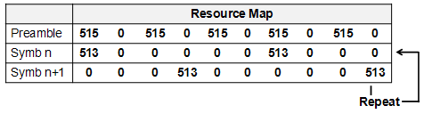
- Resource Map file: because the preamble and pilots are used simultaneously on both antennas, it is not necessary to assign an antenna number. Instead, one further bit is used in the Resource Map value to indicate that the given resource is present on all antennas. This is bit #10, which means that a multi-antenna resource will have a value of (512 + Resource Type).
For the simplified MIMO signal above, the Resource Map would be:
- Resource Modulation file: this file requires no modification; as before, it contains one Resource Modulation value for each subcarrier shown in the Resource Map file.
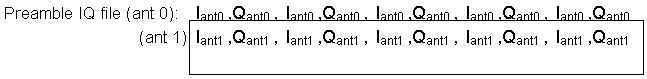
- Preamble and Pilot IQ files: although the preamble and pilot subcarriers are present on both antennas simultaneously, they will generally not have the same I-Q values, so they must be specified separately. In their respective IQ files, the complete set of IQ data for antenna 0 is provided first, followed by the IQ data for antenna 1, and so on.
The analyzer assumes that the number of antennas to be analyzed is equal to the number of hardware inputs currently selected on the analyzer’s Input Channels menu.
The Preamble IQ file for the simplified MIMO signal will thus include two lines, one for antenna 0 and one for antenna 1. Each line contains the I-Q pairs that describe the five preamble tones on that antenna:
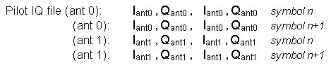
Likewise, the Pilot IQ file for this signal will contain data for two symbols on antenna 0 (because of the two-symbol repeat sequence), followed by data for two symbols on antenna 1.
See Also
Selecting the Custom OFDM Demodulator
Troubleshooting Custom OFDM Measurements