145G Rapid Prototype Phased Array Antenna – Option 360 IMPORTANT! 85571A-028 (28 GHz 5G Phased Array Antenna) accessories not suitable for use in wet locations. PAA mode is compatible with the frequency converter heads, but cannot apply or edit the frequency head corrections. Refer to “Utilities” on page 862. Learn more, refer to https://www.keysight.com/us/en/assets/9018-04847/user-manuals/9018-04847.pdf (N9938-90005). The FieldFox can be used with both VDI and OML frequency extender. Refer to “Utilities” on page 862, the Configuration Guide at: https://www.keysight.com/us/en/assets/7018-06515/configuration-guides/5992-3701.pdf (5992-3701EN), and to “Contacting Keysight” on page 5.
Option 360 measures signals at the SA RF Input Port 2 connector.
Option 360 requires the FieldFox to have SA mode (Option 233 on combination analyzers), and GPS (Option 307) installed.
Recommended, but not required, preamplifier (Option 235) to improve receiver sensitivity.
Keysight's FieldFox handheld analyzer (with Option 360) combined with a Ball Aerospace / Anokiwave 64-element antenna array provides a unique, portable solution for measuring and analyzing the 5G air interface in the field.
— Reduce measurement complexity with integrated RF probe and phased array solution to capture energy radiated from gNB
—Calibrated metrology milli-meter wave phased array antenna simulates 5G UE antenna performance
—Troubleshoot the 5G radio access network with 3D test coverage and path loss measurements utilizing the built-in CW generator
—Phased array performance verification showing bore sight, polar antenna pattern with compass, heat map and beam sweep to map display views
—“How to Define a Set Up a Scan and Use Option 360” on page 467 |
—“To change Data Logging Configuration settings:” on page 478 |
“Other Features Available” on page 480 —Alignments (SA chapter) – “Alignments” on page 219 —External Gain (SA chapter) – “External Gain” on page 166 —Field Strength Corrections (SA) – “How to select and edit corrections for Field Strength measurements” on page 169 —Scale Settings (Data Analysis) – “All about Scale Settings” on page 852 |
See Also
Chapter 31, “System Settings.” (Changing display colors) |
Using the Phased Array Antenna (Option 360)
Option 360 enables you to do the following:
About Phased Array Antenna Measurements
Some measurement parameters are auto-coupled and are not user-settable.
Phased Array Antenna Features (Option 360) IMPORTANT! Option 360 antenna requires a static IP address. If it is required to have available an IP address that can be accessed over your company’s network, work with your company’s IT team to set up a static IP that works over the network. IMPORTANT! If you forget you N9910X-028 Ball Antenna’s static IP address, refer to this link and the Support tab for assistance: www.keysight.com/find/fieldfox and then to the Phase Array Antenna Support Document.
Phased array antenna has the following features:
Scan Results:
—28 GHz operation
—gNB RF parametric test over-the-air in the field
—Measure EIRP (effective isotropic radiated power)
—Milli-meter wave beam sweep survey with map
—Support for real-time spectrum analysis, transmitter power and spectrum emission mask (SEM)
User can set up and display the following:
—Bore-Sight – Elevation angle is fixed. Scan azimuth –60 degrees to +60 degrees.
—Heat Map – Scan both elevation and azimuth angle with adjustable color “heat” amplitude scale.
—Polar ANT – Scan azimuth angle. Elevation is fixed.
—Park ANT – Polar image overlay load image:
—Resize polar coordinates
—Specify alignment angles
—Specify compass true north
—Define antenna direction (azimuth degrees)
Figure 14-1 Example of local point-to-point LAN connection
Figure 14-2 Bore-Sight Scan – CW RF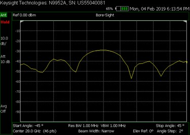
Figure 14-3 Polar Scan with compass displayed
Figure 14-4 Heat Map (Azimuth vs. Elevation) - Parked Antenna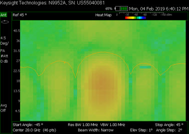
Figure 14-5 Heat Map and Undocked Active Entry – Parked Antenna
Figure 14-6 Polar Assign Orientation and Polar with Compass Orientation
Figure 14-7 Polar Measurement with Compass with Recalled Image of Indoor Auditorium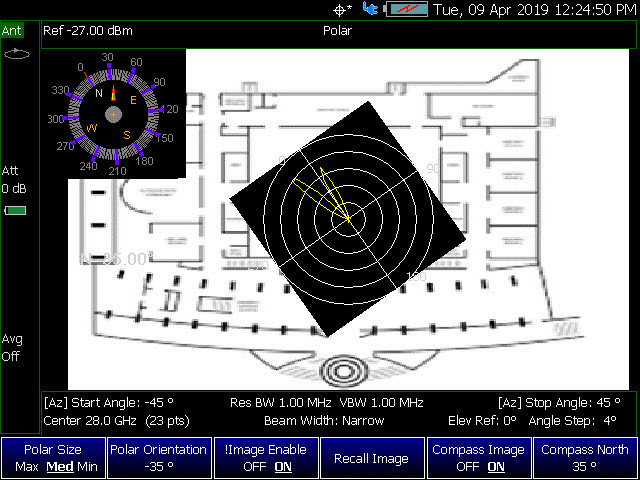
CW vs. Pulsed RF Measurements IMPORTANT! For pulsed RF measurements, increasing the Dwell Time is recommended for faster throughput and accurate signal capture in a single sweep.
Figure 14-8 Bore-Site Measurement with CW RF (Dwell Time=10 ms, Max Hold=OFF)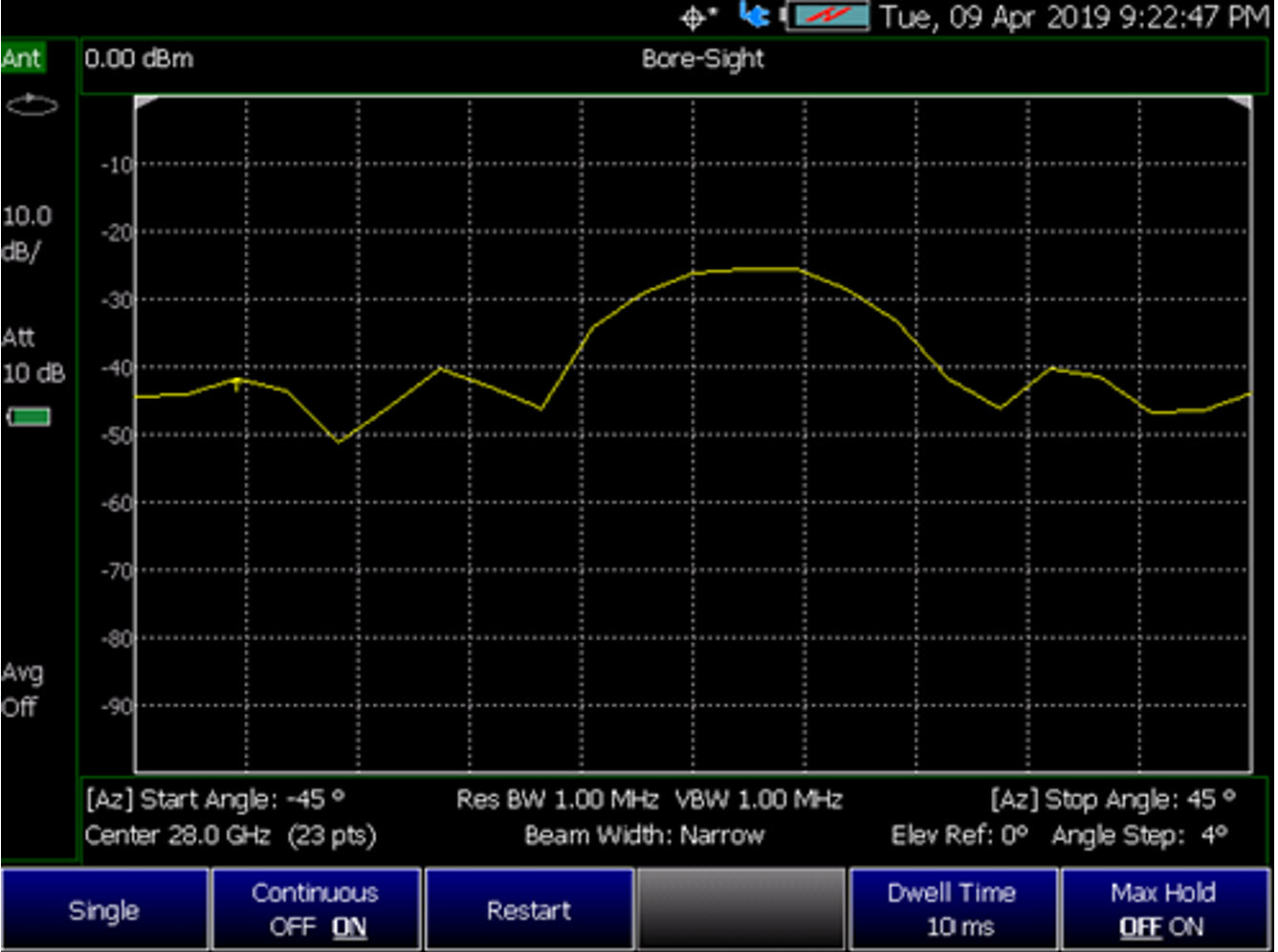
Figure 14-9 Bore-Site Measurement with Pulsed RF (Dwell Time=10 ms, Max Hold=OFF)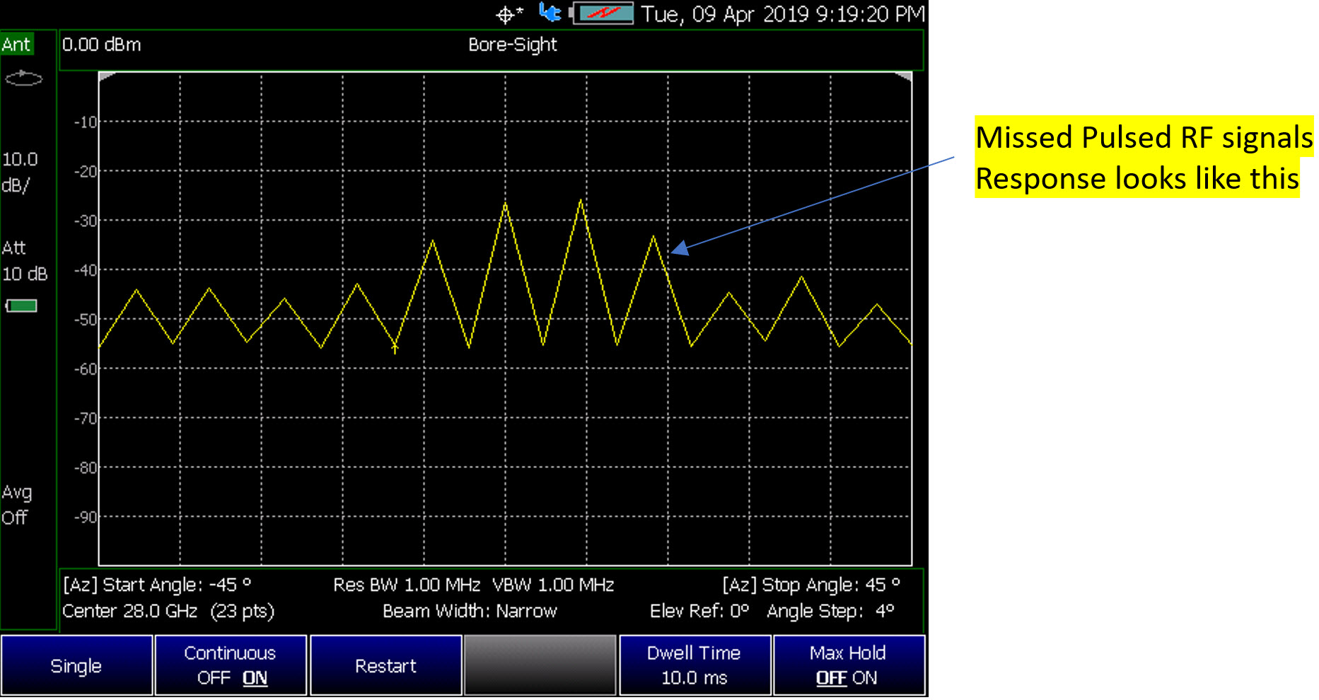
Figure 14-10 Bore-Site Measurement with Pulsed RF (Dwell Time=100 ms, Max Hold=OFF)
How to Set Up Phased Array Antenna Settings
| IMPORTANT! See also, “Alignments” on page 219, in NA mode,Chapter 9, “SA (Spectrum Analyzer) Mode (Option 233–Mixed Analyzers).” |
This section reviews the steps in setting up an Option 360 measurement. If you are not familiar with this process or would like more information, refer to “How to Define a Set Up a Scan and Use Option 360”
This section consists of:
—“Option 360 Setup Procedure”
Figure 14-11 Setting Up Option 360 Using Other Modes
1.Connect your equipment similar to Figure 14-1 on page 447.
2.Set FieldFox to use static IP address:
Press System 7
—Then System Configuration > More > Network Config
a.In the Setting screen, use the  arrows, the rotary knob, or numeric keypad to highlight Obtain IP.
b.Press Edit >Obtain IP Static
c.Press Done Edit > Done
| IMPORTANT! The LAN address for first 3 fields must match the Static IP address of FieldFox. For example, if the Ball Antenna IP address is 192.168.1.10, set FieldFox Static IP address to 192.168.1.xx. “xx” must be different number than shown in the last field of the for Ball Antenna. Refer to Figure 14-15 on page 465. IMPORTANT! If you forget you N9910X-028 Ball Antenna’s static IP address, refer to this link and the Support tab for assistance: www.keysight.com/find/fieldfox and then to the Phase Array Antenna Support Document. |
3.Selecting phased array antenna mode using the Antenna Wizard:
a.Press Measure.
b.Then Antenna Wizard
c.Follow the prompts. See Figure 14-12.
| Once the connect is correct, the FieldFox’s displayed annotation indicating "Check LAN connection. Check IP address." is no longer displayed during pinging of the Host IP address. |
Figure 14-12 Antenna Wizard Screen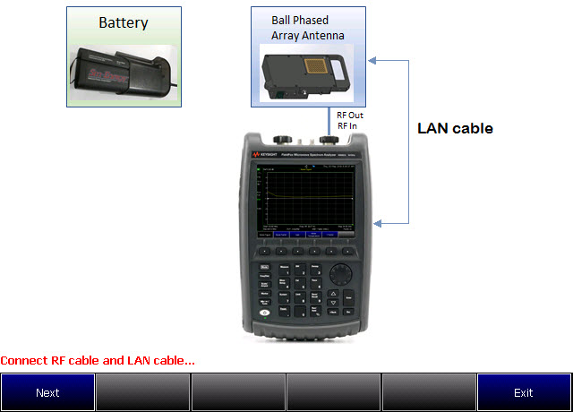
4.Aligning the antenna’s azimuth and elevation orientation:
Refer to Figure 14-14 on page 458.
Figure 14-13 Site Wide LAN Configurations and Field Measurements Configurations
Figure 14-14 Site Wide LAN Configurations and Field Measurements Configurations
5.Entering the phased array antenna measurement type:
Refer to “Data Formats:” on page 446.
Select Measure:
—Measure—choose:
—Bore-Sight or
—Heat Map or
—Polar ANT or
—Park ANT
6.Using the table to enter phased array antenna settings, presetting the antenna, setting the antenna LAN IP, and clearing the graphics:
Refer to Figure 14-16 on page 466.
Select Meas Setup:
—Antenna Settings—choose:
—Ball Antenna > LAN Address
—Settings–choose:
——Res BW or
——Video BW
——Beam Width
—Array Antenna–choose:
——Center
——Azimuth Ref
——Elevation Ref
—Polar Display >Ref
—Sweep > Dwell Time (Optional. For pulsed RF measurements it is recommended that the Dwell Time is increased.)
—Sweep > Max Hold (Optional. For pulsed RF measurements it is recommended that Max Hold is set to OFF when using the Heat Map display. (Default = OFF).)
—Preset Antenna presets the antenna settings factory defaults.
—Ant LAN IP enter the Ball antenna’s LAN IP. First three fields must match the FieldFox’s static IP address (default: 192.168.1.10). Refer to Figure 14-15 on page 465.
—Clear Graphics If applicable, this clears the current displayed PNG graphic from the screen.
| If after making the setting changes in the steps below, no data is displayed, refer to “Troubleshooting” on page 481. |
7.User markers to identify azimuth and elevations settings:
Select Marker –choose:
—Marker 1 2 3 4 5 6 – You can set up to six markers. The OFF, Normal, Delta, or Peak softkey is black to indicate the current setting of each marker.
—Normal displays a marker.
—Delta displays a marker relative to another active marker.
—Peak displays a marker on the peak point of the displayed trace.
—More – choose.
—Marker Trace – You can set up to four traces.
—Marker Table – Enable or disable the marker table that displays the current markers and their values.
Learn more about markers. Refer to the Chapter 30, “Data Analysis Features.”.
See also Figure 14-5 on page 450.
8. Enable the Data Logging settings:
—Press Trace 6 > Data Logging then
—Record (Outdoor Logging) or
—Play (If you have previously stored data recordings.) or
—To set Data Logging—choose:
a.Record Settings (Outdoor Mapping only) – then choose:
—Optional: Then Meas Interval > ON
—Then Interval Type > choose Time or Distance.
—Then, if applicable Time Interval enter time interval in seconds.
Or
—Then, if applicable Distance Interval enter distance interval in miters.
—Then Back
b.Record Save/Recall (If you have previously stored data recordings.)
—Save Log File or
—Recall Log File or
—User Folder Def System (Default = Default) or
—File Type (Default = KML) CVS or DREC (DREC is only available with Option 360 only)
—Then Auto Save OFF ON (Default = OFF).
| Spectrum information is not recorded. Only the TableChart data are saved. See “How to Record a Data Log” on page 478. |

| Data Log-Play files are saved to: —If File Folder is set to Default then Data Log-Play files are save-recalled to: "[CurrentDevice]\RecordPlayback\PAA" —If File Folders are set to System, then Data Log-Play files are save-recalled to: "CurrentDevice\<UserSelectedFolder>\ |
| Learn more about file settings, refer to Chapter 33, “File Management.”. |
c.Indoor Map Data Logging - then Record Indoor Data or Recall Indoor Log File.
—Then choose Navigate OFF ON, Data Selection, Zoom, Pan, Record Data, More
9.Press Back to return to previous menu.
— Pause Resume Temporarily halts recording until pressed again. The incoming trace continues to sweep. Press again to continue recording.
—Stop Immediately
—The Save the log file menu opens. Edit the filename and press Done to exit menu. See Settings below and “To change Data Logging Configuration settings:” on page 478.
—To change your file settings or measurement interval. Learn more, refer to “To change Data Logging Configuration settings:” on page 478.
—(Press Record to begin a new recording.)
—Then Maps To enable map view and related features (e.g., Data Selection, Red/Blue Limits, Labels & Icons, Zoom).
Then choose from the following:
—View Map OFF ON To enable/disable the current map view (default = latitude/longitude = 0.00/00. Need GPS to view current location (default = OFF).
—Data Selection Opens a softkey menu to set the active data channel, sort type, and sort order.
Learn more, refer to Chapter 16 Mapping and “Setting up Data Logging” on page 527. See also, Chapter 33, “File Management.”
—Red/Blue Limits Opens a softkey menu to assign power values to the red (high power limits) and blue (low power limits) heat map display limits (defaults: Red Limit = –20 dBm, Blue limit = –90 dBm).
—Labels & Icons Opens a softkey menu to enable/disable map data point labels and icon types.
Labels OFF ON | Enables/Disables map data point labels. When enabled, a label is displayed for every map data point (e.g., “Data 1”). When disabled, labels are not displayed for the map data points. |
Icons | Sets the type of icon that is used to display a map’s data points. |
— Save Image (PNG) Saves the current displayed map to a *.png file (default filename is “MapImageFile”).
Data Log-Play files are saved to: —If File Folder is set to Default then Data Log-Play files are save-recalled to: "[CurrentDevice]\RecordPlayback\PAA" —If File Folders are set to System, then Data Log-Play files are save-recalled to: "CurrentDevice\<UserSelectedFolder>\ |
11. Export KML file into 3rd party mapping software (i.e., Google Map or Google Earth). Refer to “Step 7: Import and Play back KML Files into 3rd Party Software (Example: Google Earth with Animation Tool)” on page 475.
12. Select Trace 6—choose:
For this step, refer to Figure 14-6 on page 451.
—Polar Size Max Med Min Sets the size of the polar display. Smaller sizes used to overlay PNG maps. (Default = Max)
—Polar Orientation Aligns the antenna polar display to a selected direction.
—Image Enable OFF ON (Optional to overlay antenna bore-sight direction. Only active if you have recalled a PNG image to display on the FieldFox as a map. (Default = OFF)
—Recall Image Use to recall PNG map to overlay antenna direction.
—Compass Image OFF ON To display a compass indicating true north for antenna. (Default = ON)
—Compass North Use this softkey to align the compass’ true north value in degrees.
Repeat process as needed for additional settings.
13. Optional: Press Freq/Dist
—Press Antenna Settings opens the table antenna settings softkey menu, where you can define your phased array antenna settings, Ball Antenna: LAN address, Settings: Resolution BW, Video BW, Beam Width, Array Antenna: Center frequency, Azimuth Ref, Elevation Ref, and Polar Display: Ref. For details, refer to step 6 above.
—Then Start Azimuth +/-45 degrees. (Default = 45 degrees)
—Then Stop Azimuth +/-45 degrees. (Default = 45 degrees)
—Then Ref Elevation +/-45 degrees. (Default = 0 degrees)
14. Optional: choose change sweep, dwell time, and max hold settings:
Press Sweep
Then choose:
—Dwell Time to set the delay between the antenna positioning from 1 ms to 10 seconds (default: 10 ms). For pulsed RF measurements it is recommended that you increase the Dwell Time to ~100 ms.
—Max Hold For pulsed RF measurements, it is recommended that Max Hold is set to OFF when using the Heat Map display.
(Default = OFF)
—Single
—Continuous to enable or disable the continuous sweep (default: ON).
Learn more, refer to Chapter 9, “SA (Spectrum Analyzer) Mode (Option 233–Mixed Analyzers).”
—Restart
15. Optional: choose devices and save files:
Press Save/Recall
Then choose:
—Save to set the attenuator power (default: –10 dB). Set to 0 dB.
—Recall change to ON.
—Device to set the absolute power (dBm)
—File Type then choose:
—State Saves the current state settings
—Trace+State Saves the current Trace+State information
—Picture (PNG) to save the current displayed trace as a PNG
—Data (CSV) save files as a CSV file
Learn more, refer to Chapter 33, “File Management.”
16. Optional: Modify scale and amplitude values:
Press Scale/Amptd
Then one of the following:
—Autoscale Automatically adjusts the Y-axis minimum and maximum values.
—Scale Manually enter a scale per division values.
—Others: Scale, Ref Level, etcetera as desired.
Learn more, refer to Chapter 30, “Data Analysis Features.”
17. Optional: Modify the averaging and Integrated BW settings:
Press BW
Then one of the following:
—Average Enable OFF ON
—Average Count
—Integ BW
Learn more, refer to Chapter 30, “Data Analysis Features” and Chapter 9, “SA (Spectrum Analyzer) Mode (Option 233–Mixed Analyzers).”
Figure 14-15 Example of Phased Array Antenna and FieldFox Static IP Setup - First Three Static IP Fields Are the Same
Figure 14-16 Example Antenna Settings Table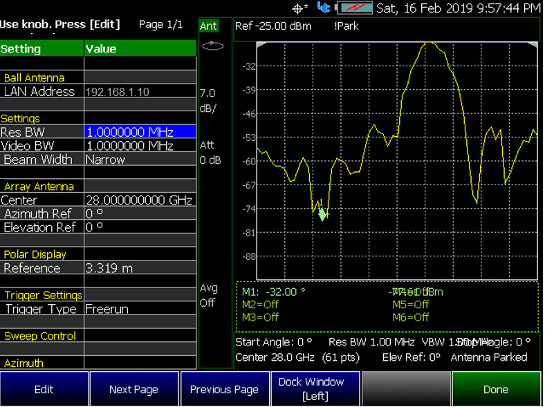
How to Define a Set Up a Scan and Use Option 360
You can define measurements by selecting which type of data to display.
Data definitions consist of the following:
—Select the measurement type
—Define the antenna setting, using the antenna settings table
—Define other optional marker, sweep, averaging, bandwidth settings
Example: Refer to:
—“Step 1. Connect Your Equipment” on page 467
—“Step 2. Set FieldFox to Use Static IP with Your Ball Antenna” on page 467
—“Step 3. Define the measurement” on page 468
Then:
—“Step 4: Select Polar Settings” on page 470
—“Step 5. Modify Scale and Attenuator Settings” on page 470
—“Step 6: Enable Data Logging and Playback the Results” on page 471
Step 1. Connect Your Equipment
Connect your equipment similar to Figure 14-1 on page 447.
Step 2. Set FieldFox to Use Static IP with Your Ball Antenna IMPORTANT! The LAN address for first 3 fields must match the Static IP address of FieldFox. For example, the Ball Antenna’s factory IP address is 192.168.0.10, set FieldFox Static IP address to 192.168.0.xx. “xx” must be different number than shown in the last field of the for Ball Antenna. Refer to Figure 14-15 on page 465. IMPORTANT! If you forget you N9910X-028 Ball Antenna’s static IP address, refer to this link and the Support tab for assistance: www.keysight.com/find/fieldfox and then to the Phase Array Antenna Support Document.
—The Ball antenna’s default static IP address is: 192.168.1.10
—Set FieldFox to use static IP address:
Press System 7
—Then System Configuration > More > Network Config
1.In the Setting screen, use the arrows, the rotary knob, or numeric keypad to highlight Obtain IP.
2.Press Obtain IP Static
3.Press Clear, then set the Static IP Address to: 192.168.1.2
and
4.Press Done
5.Press Clear, then set the Static Subnet Mask to: 255.255.255.0
and
6.Press Done
7.Press Clear, then set the Static Gateway to: 192.168.1.254
and
8.Press Done
9.Using the arrows, the rotary knob, or numeric keypad to select Apply Settings.
10. Press Edit, then select Now.
11. Press Done Edit > Done
Step 3. Define the measurement
1.Press Preset then Mode Preset (Factory)
2.Selecting Phased Array Antenna mode: Press Mode > Phased Array Antenna. Depending on the number of options loaded on your FieldFox, it may be necessary to press More.
3.Optimizing the FieldFox to scan for signals:
a.Run the Antenna Wizard: Measure > Antenna Wizard and follow the prompts.
b.Set the Measure type (i.e., Bore-Sight, Heat Map, Polar ANT, or Park ANT).
See also “How to Set Up Phased Array Antenna Settings” on page 455.
c.Set the Meas Setup > Antenna Settings table:
—Ball Antenna: LAN address
—Settings: Res BW, Video BW, and Beam Width
—Array Antenna: Center frequency, Azimuth Ref, and Elevation Ref
—Polar Display: Ref
See also “How to Set Up Phased Array Antenna Settings” on page 455.
d.Optional: Measure > Data Logging:
—Record Settings (Outdoor Mapping only) then choose
—Measure Interval OFF ON
—Interval Type Time Distance
— Time Interval if applicable (only active when Interval Type = Time) or
—Distance Interval if applicable (only active when Interval Type = Distance)
—Auto Save OFF ON
—Back to return to previous menu
e.Record Save/Recall (Save Log File, Recall or
f.Record or
g.Play if you have a previously stored data scan
See also “How to Set Up Phased Array Antenna Settings” on page 455 and “Step 6: Enable Data Logging and Playback the Results” on page 471.
Learn more, refer to Chapter 16 Mapping and “Setting up Data Logging” on page 527
h.Optional: Press Sweep 3 and modify/select items:
—Single
—Continuous OFF ON to ON (default)
—Restart
—Dwell Time For pulsed RF measurements, it is recommended that the Dwell Time is increased to ~100 ms.
Default = 10 ms.
—Max Hold For pulsed RF measurements, it is recommended that Max Hold is set to OFF when using the Heat Map display.
(Default = OFF)
| IMPORTANT! It is not sufficient to be locked to the GNSS satellite, the frequency reference must be locked to GPS. Refer to Chapter 31, “System Settings” and then to “How to make GPS settings” on page 886. |
Select one of the following display orientations:
Select Trace 6—choose:
For this step, refer to Figure 14-6 on page 451 and see also “How to Set Up Phased Array Antenna Settings” on page 455.
—Polar Size Max Med Min or
—Polar Orientation or
—Image Enable OFF ON or
—Recall Image or
—Compass Image OFF ON or
—Compass North or
Step 5. Modify Scale and Attenuator Settings
To set the scan’s scaling and receiver corrections:
Learn more, see “How to select and edit corrections for Field Strength measurements” on page 169.
1.Press Scale/Amptd >Corrections then choose:
—Apply Corrections OFF ON
—RcvrSide Antenna then choose:
—Antenna OFF ON
—Edit Antenna
—New
—Save Antenna
—Recall Antenna
—Storage Device
—RcvrSide Cable then choose:
—Cable OFF ON
—Edit Cable
—New
—Save Cable
—Recall Cable
—Storage Device
2.Press Scale/Amptd then choose:
—Autoscale
—Unit dBm
—External Gain
—External Gain
Step 6: Enable Data Logging and Playback the Results
| Spectrum and Strip Chart information is not recorded. Only the Table and Bar Chart data are saved. See “How to Record a Data Log” on page 478. |
Data Logging creates a record of your data with a timestamp and GPS stamp (refer to “GNSS (GPS+) and GPS” on page 886). GPS must be enabled for the log results to include a GPS stamp or use Preferences to enable the timestamp. Refer to Chapter 31, “System Settings.”
Features
—Log files contain cell results for different component carriers (CCs) including timestamps and/or distance stamps.
—Timestamps are included in log files with or without GPS.
—GPS must be enabled for log altitude results.
See also “GNSS (GPS+) and GPS” on page 886.
—Data results can be logged
—Data results can be saved to a *.CSV, DREC (Option 360 only), or *.KML file. Refer to “” on page 475.
—User specifies how often results are stored.
—Time: Store results every “n” seconds
—Altitude: Store results every “n” meters. GPS must be enabled to store results by altitude.
Procedure
1.Press Trace 6 > Data Logging to view the Data Logging softkeys and set the Record Settings, Record Save/Recall, and Indoor Map Data Logging.
—Record (Outdoor Logging) or
—Play (If you have previously stored data recordings.)
a.Outdoor Mapping only: To set the Record Settings—choose:
—Meas Interval
—Interval Type Time or Distance
—Time Interval or
—Distance Interval
b.Then press Record Save/Recall
—Then File Folder Default System
—Default – Sets the default User Folder path:
——List files (*.csv and *.kml) are save-recalled to: "[CurrentDevice]:\RecordPlayback\PAA\"
——Data Log-Play files are save-recalled to: "[CurrentDevice]:\RecordPlayback\PAA\"
Or
—System – Sets the User Folder to the user defined system folder path/name:
——List files are save to-from "CurrentDevice\<UserSelectedFolder>\"
——Data Log-Play files are save-recalled to: "CurrentDevice\<UserSelectedFolder>\"
Refer to “File Management” on page 913.
—Then File Type
— KML (default) or
—CSV
—DCREC (Option 360 only)
| Three file types are supported for save or recall log results: —KML file format ——Files stored in this format can be imported into 3rd party applications like Google Earth or Google Maps. —CSV file format. Files stored into this format can be imported into spreadsheet applications. —DREC file format. This file type is a binary file. File contains recorded state and trace data, with GPS time and locations stamps if enabled. Available with Option 360 only. |
—Then Save Log File.
or
—Then Recall Log File.
—Auto Save (default = OFF)
—Then Back
c.Optional: Press Indoor Map Data Logging then
— Record Indoor Data or Recall Indoor Log File. Learn more, refer to “How to Use Data Logging/Playback (Option 360)” on page 476, Chapter 16 Mapping and “Option 352 Indoor Maps Setup Procedure” on page 515.
—Then choose from Navigate OFF ON, Data Selection, Zoom, Pan, Record Data, More
—Learn more, refer to Chapter 16 Mapping and “Setting up Data Logging” on page 527.
2.Press Back to return to previous menu.
3.Outdoor Mapping: Press Record to begin a new recording and then
— Pause Resume Temporarily halts recording until pressed again. The incoming trace continues to sweep. Press again to continue recording.
—Stop Immediately stops recording and a “Save the Log File” menu opens to rename and save your data log file.
—(Press Record to begin a new recording.)
—Then Maps To enable map view and related features (e.g., Data Selection, Red/Blue Limits, Labels & Icons, Zoom).
— View Map OFF ON Displays the current GPS location.
—Data Selection Opens a softkey menu to set the active data channel, sort type, and sort order. See also previous steps 10 in “How to Set Up Phased Array Antenna Settings” on page 455.
—Red/Blue Limits Opens a softkey menu to assign power values to the red (high power limits) and blue (low power limits) heat map display limits (defaults: Red Limit = –20 dBm, Blue limit = –90 dBm).
—Labels & Icons Opens a softkey menu to enable/disable map data point labels and icon types.
Labels OFF ON | Enables/Disables map data point labels. When enabled, a label is displayed for every map data point (e.g., “Data 1”). When disabled, labels are not displayed for the map data points. |
Icons | Sets the type of icon that is used to display a map’s data points (default = Flag). |
— Save Image (PNG) Saves the current displayed map to a *.png file (default filename is “MapImageFile”).
4.When done press Stop. The log file is automatically saved to the defined Device Type and File Type.
Else, edit the User Folder and File Type, under Record Save/Recall where the file results will be stored.
Learn more about file settings, refer to the Chapter 33, “File Management”. |
5.Press Back
Playing a Data Log and Viewing the Data
To play the log results:
1.Press Record Save/Recall > Recall Log File
And, use the Use the RPG or the arrow keys to highlight the file to be played.
2.Press Recall File > Back > Play
3.Press Stop to exit the log playing.
To pause the log play:
1.Press Pause Resume to pause or resume the log playing.
2.Press Stop to stop the log playing.
Learn more, refer to Chapter 16 Mapping and “Setting up Data Logging” on page 527. See also, Chapter 33, “File Management.”
Step 7: Import and Play back KML Files into 3rd Party Software (Example: Google Earth with Animation Tool)
Features
Use the Playback Slider to replay measurement results. See also Google Maps and or Google Earth’s help. Refer to Figure 14-17 on page 475.
—Open the FieldFox *.KML file in Google Earth. The time slider appears in upper left of the map.
—Manual Mode – Move the time slider cursor to see color-coded icons pop-up according to the timestamp.
—Loop mode has a Fast-Slow Replay Option.
—Click on each color coded balloon to see the table of measurement results for that location.
Figure 14-17 Importing a KML File Into Google Earth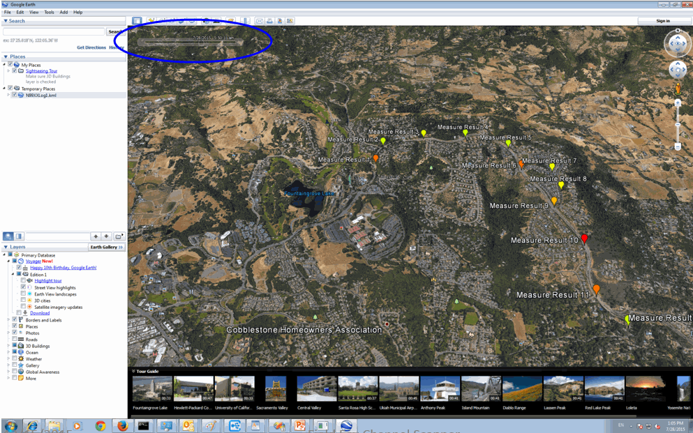
How to Use Data Logging/Playback (Option 360)
| Data log-Play files are saved to: —If File Folder is set to Default then Data Log-Play files are save-recalled to: "[CurrentDevice]\RecordPlayback\PAA" —If File Folders are set to System, then Data Log-Play files are save-recalled to: "CurrentDevice\<UserSelectedFolder>\ |
Data Logging and Playback enables you to log phased array antenna trace data and play them back at a later time. Use this feature to monitor table data activity over a period of time.
Data logs can be saved to the FieldFox Internal memory, an SD Card, or a USB flash drive.
This section assumes you have already completed the initial setup and have a phased array antenna scan displayed on the FieldFox.
Screen Annotation
During a data logging or playback session, the following is displayed in the top-center area of the screen:
— Rec: 55/55 2018-12-31 03:26:11 PM
where:
—55/55 is the current and total trace number: currently trace is 55 of 55 total scans.
—2018-12-3103:26:11 PM is the date and time of recording.
—The name of a recording can be changed using Manage Sessions. Learn more in “To change Data Logging Configuration settings:” on page 478.
See also, the FieldFox User’s Guide’s “System Settings” chapter.
When GPS is enabled , GPS R is indicated at the bottom of the FieldFox display. Learn more, see the FieldFox User’s Guide’s “System Settings” chapter.
The Phased Array Antenna mode can display and be data logging/played back in field strength units, when the units are changed:
—Press Scale /Amptd > More > Unit then choose:
—dBmV, dBuV, W, V, A, dBmA, or dbuA (Default Units: dBm)
Figure 14-18 Field Strength Annotation that can be Logged and Played Back
| If Data Logging or Playback is not occurring when you think it should, check the following: —Is the sweep in HOLD? (upper-left annotation), or check the Sweep menu for Continuous set to OFF. —Is Recording or Playback Paused? (mid-left annotation) —Is the Data Logging or Playback Interval set too long? (Configuration settings.) |
How to Record a Data Log Data Log-Play files are saved to: —If File Folder is set to Default then Data Log-Play files are save-recalled to: "[CurrentDevice]\RecordPlayback\PAA" —If File Folders are set to System, then Data Log-Play files are save-recalled to: "CurrentDevice\<UserSelectedFolder>\
—Press Trace 6
—Then Data Logging
—Then Record
is displayed in the left of screen graticules.
During recording, choose from the following:
—Pause Resume Temporarily halts recording until pressed again. The incoming trace continues to sweep. Press again to continue recording.
—Stop Immediately stops recording. Then choose from the following:
—Then Record Save/Recall To save a log file, recall log file, or change your file settings. Learn more, refer to “To change Data Logging Configuration settings:” on page 478.
——Press Save Log File to save the current Table data (i.e., default save device is Internal).
—Then Record Settings (Outdoor Logging) To change your measurement interval settings. Learn more, refer to “To change Data Logging Configuration settings:” on page 478.
To change Data Logging Configuration settings:
—Press Trace 6
—Then Data Logging then choose:
—Then Record Settings (Outdoor Mapping Only)
—Optional: Then Meas Interval > ON
——Then Interval Type > choose Time or Distance.
——Then, if applicable Time Interval enter time interval in seconds.
Or
——Then, if applicable Distance Interval enter distance interval in miters.
—Then Record Save/Recall
—Then Device (Internal (default), SD Card, or USB)
—Then File Type (CSV, DREC (Option 360 only), or KML (default))
Learn more, refer to the Chapter 33, “File Management”.
—Press Trace 6
—If the session is already open, skip the following step. Otherwise:
—Then Data Logging > Record Save/Recall
| If these are large recordings on a device, it could take several seconds for the FieldFox to display the list. |
—Then Recall Log File use the Use the RPG or the arrow keys to highlight the file to be played.
——Then Recall File
——Then Back
—Then Play to playback your Table data.
 is displayed in the left of screen graticules during playback. When the end of the recording is reached, playback begins at the start of scan and continues to loop indefinitely.
During playback, choose from the following:
—Pause Resume Temporarily halts playback. Then choose from the following:
—Pause Resume Press to continue playing.
—Stop Immediately stops playback. Then choose from the following:
—Play Start playback from start of scan.
—Recall Log File Opens a list of stored data files.
Select a file to playback.
—Recall File
—Back
—Cursor Position use this softkey to move the data log play cursor in the current data log being played (i.e., Cursor Position is active only when playback is paused).
This softkey is only available in Channel Scanner and Phased Array Antenna modes (i.e., The Cursor Position softkey is not available for OTA mode).
—Red Limit to edit the red limit dBm value.
—Blue Limit to edit the blue limit dBm value.
The Phased Array Antenna mode has indoor and outdoor mapping capability. Refer to Chapter 16, “Indoor and Outdoor Mapping – Option 352 (Requires Spectrum Analyzer Mode (Option 233), and GPS Receiver (Option 307)).”
Other Features Available
—Alignments - For information on using alignments, refer to the SA chapter’s section, “Alignments” on page 219.
—External Gain - Refer to refer to the SA chapter’s section, “External Gain” on page 166.
—Field Strength Corrections – “How to select and edit corrections for Field Strength measurements” on page 169
—Scale Settings – For information on using scale settings, refer to the Data Analysis chapter’s section, “All about Scale Settings” on page 852 (not all of the settings apply to OTA Option 360).
Troubleshooting
If your Phased Array Antenna setup is not behaving as expected:
—Verify setup is correct by referring to “How to Set Up Phased Array Antenna Settings” on page 455.
—Attenuator set to 0 dB
—Preamplifier set to ON
—Correct Band, Channel, and Center Frequency entered
—GNSS set to Internal
—Frequency Ref set to GPS
—ADC errors: Use Scale/Amptd > Range to adjust the absolute power level (dBm).
For some data views, you need to press More to view the Range softkey.
—No data displayed: Press Meas Setup 4 then
——Verify the correct Antenna Settings have been entered.
—The FieldFox’s displayed annotation indicates "Check LAN connection. Check IP address." during pinging.
Verify:
——The LAN address for first 3 fields matches the Static IP address of FieldFox. For example, if the Ball Antenna IP address is 192.168.1.10, set FieldFox Static IP address to 192.168.1.xx. “xx” must be different number than shown in the last field of the for Ball Antenna. Refer to Figure 14-15 on page 465.
——Power is connected to the PAA. If the power is not connected indicator is flashing () on the left side of the FieldFox display, verify your connections.
| IMPORTANT! If you forget you N9910X-028 Ball Antenna’s static IP address, refer to this link and the Support tab for assistance: www.keysight.com/find/fieldfox and then to the Phase Array Antenna Support Document. |