15USB Antennas – Full Capability Requires EMF Option 358, and either SA mode (Option 233 Mixed Analyzers) or OTA—LTE FDD (Option 370), LTE TDD (Option 371), 5G NR / 5G NR EVM Conducted / 5G TF (Option 378)
Triaxial USB antennas (also, referred to as EMF antennas) can be used without EMF Option 358, but with limited capability and doing so is not recommended or supported by Keysight. |
IMPORTANT! EMF is only compatible with LTE FDD (Option 370), LTE TDD (Option 371) and 5G NR/5G NR EVM Conducted (Option 378) and SA mode (Requires Option 233—combination analyzers). User data channels are not demodulated. |
The antenna operation for single-polarization measurements is different between ARIA6000 and FSH3D. Please consult the datasheet corresponding to each antenna for specific details. |
EMF antennas measures signals at the SA RF Input Port 2 connector.
EMF antennas mode requires the FieldFox to have SA mode (Option 233 on combination analyzers), EMF (Option 358), GPS (Option 307), and CPU2 installed.
Recommended, but not required, preamplifier (Option 235) to improve receiver sensitivity.
With EMF antennas, Option 378 (5G NR) and P/O: Option 378 (5G NR EVM Conducted / 5G TF) network designers can ensure that networks have enough resources to carry out handovers (re-selection) when users move between cell towers on the same 5G network as well as in between 5G and 4G networks (intra/inter-radio access technology). The FieldFox OTA measurements support LTE FDD (Option 370), LTE TDD (Option 371), 5G NR (Option 378) / 5G NR EVM Conducted (P/O: Option 378) / 5G TF (P/O: Option 378) and over-the-air demodulation of single acquisition, multiple cell towers, or multiple acquisitions for multiple component carriers (CCs). Additionally, 5G NR / 5G NR EVM Conducted among other 5G NR capabilities, has new FR1 and FR2 spectrums. The FieldFox display can be configured to show data formats such as table, bar chart, spectrum and strip chart of key performance indicators (KPI's).
By integrating over-the-air (OTA) measurements with cable and antenna test (CAT), full 2-port vector network analysis, spectrum analysis, and real-time spectrum analysis (RTSA), the FieldFox can be used for base station setup and verification.
With EMF Antennas (P/O EMF measurements – Option 358):
— Reduce measurement complexity with a triaxial antenna to capture energy radiated from gNB
—Calibrated metrology milli-meter wave triaxial antenna simulates 5G UE antenna performance
—Troubleshoot the 5G radio access network with 3D test coverage and path loss measurements utilizing the built-in CW generator
—Triaxial antenna performance verification showing bore sight, polar antenna pattern with compass, heat map and beam sweep to map display views
—Measure and display corrected field strength in RMS average power
—Antenna control and X, Y, and Z antenna factors can be downloaded via a USB for ARIA6000 antenna or import a CSV file for FSH3D antenna
Figure 15-1 FieldFox With EMF Antenna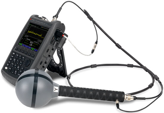
“Using USB Antennas (Also, Known as EMF Antennas)” on page 486 |
“About USB Antenna (Also, Known as EMF Antenna) Measurements” on page 487 |
“How to Set Up a USB Antenna (Also, Known as EMF Antenna)” on page 489 |
“Other Features Available” on page 494 —Alignments (SA chapter) – “Alignments” on page 219 —External Gain (SA chapter) – “External Gain” on page 166 —Record Playback – “Record/Playback (SA Option)” on page 590 —Scale Settings – “All about Scale Settings” on page 852 |
See Also
Chapter 31, “System Settings.” (Changing display colors) |
Using USB Antennas (Also, Known as EMF Antennas)
| Triaxial EMF antennas can be used without EMF Option 358, but with limited capability and doing so is not recommended by Keysight. |
EMF antennas enables you to do the following:
a.Requires Option 358 for EMF measurements. Else, antenna can be used manually with X/Y/Z axis.
USB Antenna (Also, Known as EMF Antenna) MeasurementsAbout
EMF antenna feature supports these standards:
—SA
—OTA — LTE FDD, LTE TDD, 5G NR
Some measurement parameters are auto-coupled and are not user-settable.
| For more information on the ARIA6000 EMF antenna, refer to https://www.es-france.com/index.php?controller=attachment&id_attachment=11763. For more information on the FSH3D EMF antenna, refer to https://www.schwarzbeck.de/Datenblatt/kFSH3D.pdf |
EMF antenna feature has the following features:
—SA mode automatically detect if Import antenna factors are present applies correct X/Y/Z antenna amplitude corrections for EMF measurements
—SA mode X/Y/Z factors—if available—are enabled by default
—OTA mode LTE FDD, LTE TDD, 5G NR – EMF can be manually enabled
Figure 15-2 Example Summing of Triaxial Values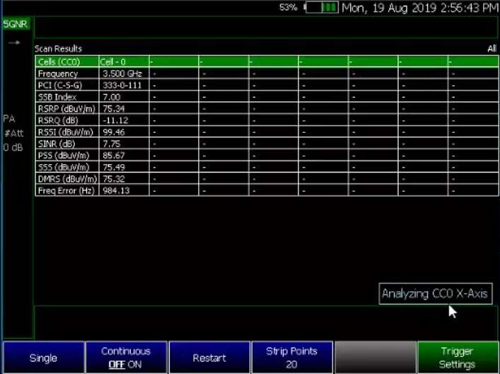
Figure 15-3 Example Verifying the Triaxial Values – Axis Y is Displayed
How to Set Up a USB Antenna (Also, Known as EMF Antenna)
| IMPORTANT! See also, “Alignments” on page 219, in NA mode, Chapter 9, “SA (Spectrum Analyzer) Mode (Option 233–Mixed Analyzers)”. |
This section reviews some general high level steps in setting up a EMF antenna measurement. If you are not familiar with this process or would like more information on specific EMF measurement setups, refer to:
1.Select the mode and set up your measurement. Refer to Chapter 13, “Over–the–Air Measurements (OTA) – LTE FDD Option 370, LTE TDD Option 371, 5G NR / 5G NR EVM Conducted / 5G TF Option 378” or to Chapter 9, “SA (Spectrum Analyzer) Mode (Option 233–Mixed Analyzers)”.
| If necessary, this step can be skipped and done after the EMF antenna is set up. |
2.Connect a EMF antenna. Refer to Figure 15-1.
| Only Agos Advanced Technologies ARIA6000 and Schwarzbeck Mess-Elektronik FSH3D Triaxial Isotropic EMF antenna is compatible with EMF (Option 358). See also Chapter 9, “SA (Spectrum Analyzer) Mode (Option 233–Mixed Analyzers)” and Chapter 13, “Over–the–Air Measurements (OTA) – LTE FDD Option 370, LTE TDD Option 371, 5G NR / 5G NR EVM Conducted / 5G TF Option 378”. |
3.Importing and selecting the X/Y/Z antenna factors: IMPORTANT! The softkey menu selection and display of Axis X, Y, Z, corresponds to Loop 1, 2, 3, respectively for EMF antenna FSH3D.
a.OTA – 5G NR and SA mode:
—Press System > Utilities > EMF Antennas >
—For ARIA6000 EMF antenna, press Antenna Select and select "ARIA6000".
Then press Import Antenna – to import the antenna factors from the antenna’s memory over the USB connection to the FieldFox (this may take 5 seconds or so and vary with the triaxial antenna). The Import Antenna softkey is only activated when Antenna Select is set to ARIA6000 or FSH3D. If the antenna factor import is successful, the FieldFox displays: “Success: Antenna Factors Imported: EMF Antenna ID: ->[R] Antenna ID: ARIA6000-1006 ->[]“. The last 4-digits will vary for each antenna (i.e., “1006” value will vary). If the FieldFox displays this error Error: EMF antenna Error: Not found or Unable to communicate with antenna. Ensure it is connected. is displayed, verify the EMF antenna is connected correctly. See also “Troubleshooting” on page 495.
—For FSH3D EMF antenna, press Antenna Select and select "FSH3D".
Then press Import Antenna > Import Files - to import FSH3D antenna factor CSV file from external storage device e.g. USB or SD Card to the INTERNAL storage. Recall File to retrieve these imported CSV files directly from INTERNAL when necessary.
Figure 15-4 FSH3D antenna factor CSV Import Files storage device selection Softkey 
Press the storage device containing FSH3D antenna factor CSV file you wish to import from. The window will navigate to the chosen storage device and display all available CSV files.
Choose a single FSH3D antenna factor CSV file from the list, then press Import.Once imported, press Done to complete the process.
To recall INTERNAL FSH3D antenna factor CSV, press Import Antenna, then select the target CSV file and press Recall File.
| FSH3D antenna factor CSV files MUST be saved in the "AntennaEMF" folder within the storage device to import from. |
—By selecting Antenna Select and choosing either ARIA6000 or FSH3D to verify the EMF antenna selected (Default == Manual). Only compatible EMF antennas can be used for EMF measurements.
See also, “How to Use the Manual EMF Channel Power” on page 250.
—Optional: Press Antenna Axis with Auto (default) selected the FieldFox determines the X/Y/Z settings for the current measurement. Alternately, you can select either X, Y, or Z to enable and to edit a position manually (i.e., an example of editing X, Y, and Z axes is covered in step 5). The Antenna Axis softkey is only activated when Antenna Select is set to ARIA6000 or FSH3D.
4.If you have not selected a mode and set up your measurement, then do so now. Refer to step 1.
5.Enabling the imported EMF antenna factors and Cable factors:
Choose one of these:
6.If you need to edit or add new antenna factors or cable factors, then repeat step 5 as required for Y, Z, and the Cable Factors. See also, “How to Set Up EMF Settings (Requires EMF (Option 358), GPS (Option 307), and SA Mode (Option 233–Mixed Analyzers))” on page 242 and “How to Set Up EMF Mode Settings (Requires EMF (Option 358) and LTE FDD (Option 370), or LTE TDD (Option 371), or 5G NR (Option 378))” on page 420.
7.Once you have finished with your EMF antenna setup:
a.Press Sweep 3 > Single > Restart
The FieldFox should display in order Analyzing CCO X-Axis, Analyzing CCO Y-Axis, and Analyzing CCO X-Axis and then do a square root sum of the X, Y, and Z measurement values in the FieldFox. Multi-cell measurements are done similarly for each cell ID (i.e., Cell CC0 to CCn). Refer to Figure 15-5 on page 492.
Figure 15-5 Example Summing of Triaxial Values
Figure 15-6 Example Verifying EMF 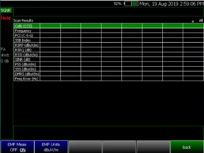
Editing Antenna Correction Factors and Adding New Antenna Factors Keysight does not recommend editing a EMF antenna’s correction factors. If New is selected under the X, Y, or Z Antenna or Cable softkey menu, whatever antenna or cable factors that have been imported as the default values and are displayed in the Settings table.
For procedures illustrating how to edit the Antenna Factors settings table values, refer to:
Figure 15-7 SA mode – Example Editing and Adding a New X axis antenna
Other Features Available
—Alignments - For information on using alignments, refer to the SA chapter’s section, “Alignments” on page 219.
—Scale Settings – For information on using scale settings, refer to the Data Analysis chapter’s section, “All about Scale Settings” on page 852 (not all settings apply to a EMF antenna.
—External Gain - Refer to refer to the SA chapter’s section, “External Gain” on page 166.
—Record Playback - Refer to refer to the Interference Analyzer chapter’s section, “Record/Playback (SA Option)” on page 590 and to the OTA chapter’s “How to Use Data Logging (OTA Options 370, 371, and 378)” on page 428.
Troubleshooting
If your EMF antenna setup is not behaving as expected:
—Verify setup is correct by referring to “How to Set Up a USB Antenna (Also, Known as EMF Antenna)” on page 489.
—If the FieldFox displays this error Error: EMF antenna Error: Not found is displayed, verify the EMF antenna is connected correctly or Unable to communicate with antenna. Ensure it is connected. Verify the antenna connection (i.e., Disconnect and reconnect the USB cable).
Press EMF Antennas > Import Antenna
If the FieldFox still displays the EMF antenna error, try a different EMF antenna.
—If you are unable to view the X,Y, and Z antenna correction factors, then:
Press Scale/Amptd > More > Corrections > Antennas Off > Antenna (Off) to On (Default == Off)
—If you are having problems with your measurement, verify the antenna corrections have been enabled:
Press Scale/Amptd > More > Corrections > Apply Corrections [Auto] (Default == Auto, enabled)
—Preamplifier set to ON