Probes/External Hardware
Probing a signal can be easy and successful if some forethought is given to the nature of the circuit under test and what type of probe best solves the measurement problem. Two issues are raised when measuring a signal with a probe:
- How the probe and instrument combination represents the signal at the probe tip
- How the probe affects the measurement
Due to a wide variety of signals that may be encountered, which range from high bandwidth (fast rise times) to high impedance, one type of probe may be more effective than another type. Therefore, it is helpful to understand the different effects caused by the interaction between the probed circuit and the probe. The response of the probe is part of the overall measurement system response. When a probe is connected to the instrument to measure a signal it becomes part of the circuit under test. The probe can then degrade the circuit under test. The new circuit will behave differently than the circuit without the probe. The following picture displays the probe as part of the circuit under test.
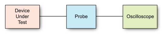
You can connect probes to the oscilloscope channel inputs, sometimes through a probe adapter.
Probe setup helps the oscilloscope accurately characterize the effects of the probing hardware so that it can display (and measure) the signal present at the probe tip.
To set up probes:
-
Connect the probe to a channel input. If needed, use the proper probe adapter.
-
In the channels Setup dialog box, click Probes/Ext HW... to open the Probes/External Hardware Setup dialog box.
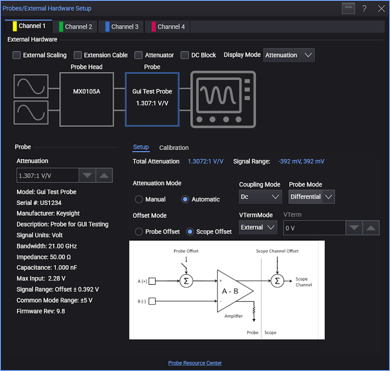
In the top External Hardware portion of the dialog box is a block diagram that shows the probing hardware blocks that exist between the device under test (DUT) signal(s) and the oscilloscope channel input. Initially, there are these blocks:
- Probe Head — If the connected probe has probe head options, selecting this block will let you choose the probe head being used. See Probe Head.
- Probe — Typically, the type of probe that is connected is automatically detected, and selecting this block will display the probe's characteristics and options in the lower portion of the dialog box (see Probe Characteristics.). However, if for example, only probe cables are being used, "No probe detected" is displayed.
- Probe Adapter or RF Adapter — When an adapter is needed to connect the probe to the oscilloscope. RF adapters may have S-parameters that need to be applied (see RF Adapter).
There are also controls that add or remove probing hardware blocks from the diagram:
- External Scaling — If any non-Keysight probing hardware is being used, this block lets you specify the associated units, attenuation/gain/dB, and offset characteristics of that hardware. See External Scaling.
- Extension Cable — Lets you select a Keysight expansion cable. See Extension Cable.
- Attenuator — Lets you select a Keysight attenuator. See Attenuator.
- DC Block — Lets you select a Keysight DC blocking capacitor. See DC Block.
For selected Keysight extension cables, attenuators, and DC blocking capacitors, their characteristics are known and automatically applied to the overall probing characteristics.
The Display Mode control lets select between Attenuation, Gain, or Gain (dB) values appearing in the dialog box.
In the lower right portion of the Probes/External Hardware Setup dialog box, you have these tabs with additional controls: