Learn about Receiver Leveling (scroll up).
Support for Pre-Sweep Mode, Point Mode, and Prior Sweep Mode
The following dialog and descriptions apply to VNAs that support pre-sweep mode, point mode, and prior sweep mode receiver leveling.
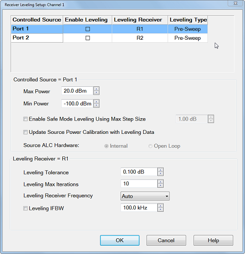
Controlled Source (Port)
Each source port to be leveled is configured individually. Select a source to be configured for receiver leveling. Choose from: Port 1, Port 2, Port 3, Port 4, or any active external source. Learn more about External Devices.
Note: A Modulation Distortion channel only allows one modulated source. Therefore, only one row will be displayed showing the name of the modulated source.
Enable Leveling - Checkbox enables/disables receiver leveling. The default is disabled (unchecked).
Leveling Receiver - Select a receiver to be used to level the specified source by clicking on the Leveling Receiver pull down menu. Choose from a VNA Receiver or Ext. Device (PMAR).
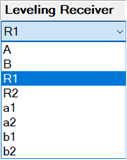
For a VNA Receiver, choose from any VNA receiver using standard or receiver notation.
To level power at the source output or DUT input choose the reference receiver for the source port. For example, to level the source power at port 1, then choose "R1". To level power at the DUT output, choose the receiver that is used to measure the DUT output. If the DUT output is connected to port 2, then select "B" or 'b2". Learn about Receiver Notation.
When Phase Control is enabled, the ratioed receivers used in Phase Control are selected and can NOT be changed. However, the Reference Source CAN also be selected for Receiver Leveling.
For Ext Device type, choose a configured PMAR device.
Leveling Type - Sets the receiver leveling type:
Pre-Sweep - Leveling sweeps are performed in the background (not visible) before every measurement sweep to measure and apply source correction data.
Point - Leveling is performed per point. If the point is outside the tolerance, the source power is adjusted and the point is read again. This process is repeated until the leveling receiver reports that the target power is within tolerance (or the maximum iteration setting is reached). When the iteration is done, it moves immediately to the next point.
Prior Sweep - Disables the receiver leveling search function. After the first sweep, receiver leveling reads the data and computes the correction for each point in an attempt to reach the target power level. The calculated offset is used for the next sweep. This process is repeated to improve receiver leveling for successive sweeps.
Controlled Source Setup
Max Power Always limits the maximum power out of the source to this value. The message: Power set to Max Power appears when this limit is reached.
If the maximum port power out of the VNA is reached at any time during the leveling sweeps, the following message appears: Power set to user power limit.
Min Power Always limits the minimum power out of the source to this value. The message: Power set to Min Power appears when this limit is reached. When Safe Mode is enabled, this value is used as the initial power level for the leveling loop process.
Note: The MAX/MIN limit is always used regardless of the safe mode state. In addition, the MAX/MIN limit is for port power and related to power offset. If the power offset is not set correctly, the MAX/MIN limit is not correct and it may impact the leveling. Ensure that the power offset in the channel is the same as power offset during calibration. If the exact power offset is not known, choose a limit for source and then it will not be related to power offset.
Enable Safe Mode Leveling Using Max Step Size
To protect your DUT and ensure stable results, these settings control the extent to which the source power will be changed to achieve the port power as measured at the reference receiver. These settings could be necessary when using external components with a large variation in frequency response (flatness).
When checked:
-
The Min source output is used as the initial power level for the leveling loop process.
-
The controlled source is never stepped more than the Max source step size.
When cleared:
-
The initial power for the leveling loop may be determined by the Min source output, the Max source output, the last setting of the leveling loop, or the target value of the leveling loop. See Initial Power below.
-
The Max source step size is ignored.
Max source step size
When Safe Mode is enabled, the change in source power at each data point from one sweep to the next is limited to this value. For example, assume Safe Mode is enabled, and Max Power Step is set to 1 dB. On the first leveling sweep, the first data point measures 3 dB lower than the port power, then source power for data point 1 will be increased by 1 dB for the next sweep, and likely for the following two sweeps.
Update Source Power Calibration with Leveling Data Available only when using an RF Source and VNA receiver.
-
When checked, the latest correction data is copied to the Source Power Cal correction array. When Leveling Mode is switched back to Internal (on the Power and Attenuators dialog), Source Power Cal is automatically turned ON using this correction data.
-
When cleared, Source Power Cal is NOT turned ON when Leveling Mode is switched back to Internal.
Source ALC Hardware (Not available on M980xA/P50xxA)
NOT available with External sources.
-
Internal- Internal ALC leveling and Receiver Leveling (Recommended).
-
Open Loop- NO ALC leveling; Receiver Leveling ONLY.
Leveling Receiver Setup
Leveling Tolerance The source is considered leveled when each stimulus data point has achieved the power level +/- (plus or minus) this tolerance value.
Leveling Max Iterations If every stimulus data point does NOT achieve the port power after this number of leveling sweeps, the measurement sweep occurs using the correction values obtained from the last leveling sweep. The message: Not settled, noisy trace appears when the Max Iterations is reached. If you see this message, you can increase the Max Iterations, reduce the IFBW, or increase the Tolerance setting.
Note: Max Iterations can no longer be set to zero. Instead, select Prior Sweep mode to disable the receiver leveling search function. In this way, there will be no pre-sweep for the receiver leveling, but the value of the receiver data will be used to correct the next sweep. This provides a post sweep correction and can be useful for correcting slow drift in a system where a booster amplifier or open loop ALC is used, without adding pre-sweeps to the sweep-acquisitions.
Leveling Receiver Frequency - Available ONLY when the selected receiver is a VNA Receiver or power meter. This setting determines which receiver frequencies are measured. Choose from:
Note: LO Leveling is not supported.
-
Auto - FOM source frequency range for reference receivers. FOM receiver frequency range for test receivers.
-
FOM Receiver - FOM Receiver frequency range. Learn more about Frequency Offset Mode.
-
FOM Source - FOM Source frequency range.
-
DUT Input - Mixer/Converter input frequency range.
-
DUT Output - Mixer/Converter output frequency range.
-
FOM Primary - Current Active Channel settings.
Leveling IFBW Available only for VNA receivers. By default, the IFBW for the leveling sweeps is set to 100 kHz. Learn more about IFBW.
-
Increase this value to make faster, but noisier leveling sweeps.
-
Decrease this value to maker slower, more repeatable leveling sweeps.
-
Uncheck the box to use the same IFBW as the measurement sweeps.
Leveling Noise BW - (SA multitone and Modulation Distortion channel only) Sets the receiver noise bandwidth value for leveling at pre-sweep. Noise bandwidth is equal to the Resolution bandwidth divided by the Vector Average factor.
Carrier Aperture Span/Offset - (SA multione Modulation Distortion channel only) Enabling the aperture settings will measure the power more quickly by reducing the span of the measurement during the pre-sweep. Enter the span and offset of the frequency aperture used to measure the signal power. Since the ideal modulation signal is known, the total power is calculated from this value.