Channel Acquisition
Use FlexRT's Configure Channel Acquisition dialog to override, for the selected channel, universal settings that configure how FlexRT interpolates and samples the channel waveform. These universal settings are made in the following Infiniium Scope Setup dialog tabs:
To turn off these shared settings and enter your unique channel settings, in this dialog clear the Shared Acquisition Parameters setting.
To open this dialog, in the UXR040X: Channels... dialog click the Acquisition button.
Symbol Rate
Enter the symbol rate in baud (Bd) of the waveform. You can either click Select From List to select a standard optical and digital telecommunications rate or click in the field and enter a custom rate. Select Auto Detect to have FlexRT automatically determine the symbol rate for the waveform.
Interpolation
Use the Interpolation settings to control how FlexRT samples the Infiniium UXR's waveform. Normally, Automatic is selected and FlexRT automatically interpolates the waveform using Sin(x)/x interpolation. When Automatic is cleared, you can choose between Sin(x)/x or turning interpolation off. Using Sin(x)/x is preferred when reconstructing a signal (having evenly spaced samples) that has been band limited.
The dialog displays the current input waveform's Acquired Samples / UI. You can directly specify the desired Samples / UI in the interpolated waveform or enter a Factor (integer value) that is used to arrive at the Samples / UI:
(Acquired Samples-per-UI) (factor) = samples-per-UI
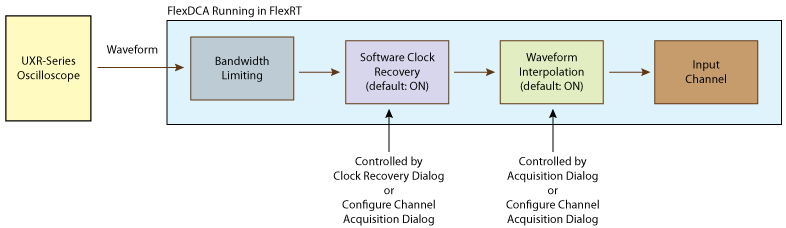
Waveform Flow from UXR Scope to FlexRT Channel
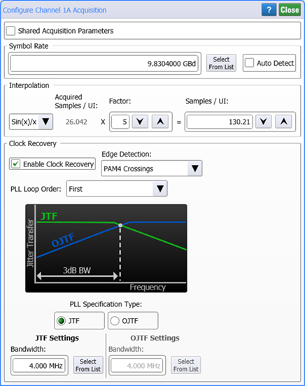
Clock Recovery
Use the Clock Recovery settings to specify how FlexRT uses its internal clock recovery when processing the Infiniium oscilloscope's input waveform. You can specify the edge detection used, the PLL's loop order, and the bandwidth for the PLL loop's Jitter Transfer Function (JTF) and Observed Jitter Transfer Function (OJTF). The loop type, JTF bandwidth, and OJTF bandwidth provide advanced control of how FlexRT constructs a clock signal from the input signal.
Select Enable Clock Recovery to have FlexRT use clock recovery. By default, this setting is selected and should normally not be cleared.
Edge Detection
The Edge Detection used during clock recovery can be set to Center Crossing or to PAM4 Crossings, which is the default setting.
PLL Loop Order
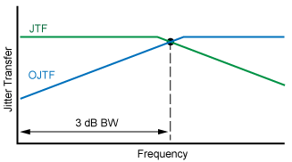
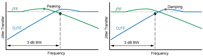
You can choose between First, Second, and Third order PLL loop types. The Jitter Transfer Function (JTF) describes how the input signal (or clock) to the DUT's PLL affects the jitter on the DUT's output signal. Jitter tracking between the DUT's input and output PLL is frequency dependent:
- Low frequency jitter is transferred to the PLL's output.
- High frequency jitter is not transferred to the PLL's output.
As the jitter on the DUT's input goes beyond the DUT's PLL loop bandwidth, and so decreases, the jitter observed on the recovered clock or signal increases. The Observed Jitter Transfer Function (OJTF) describes the transfer of the input signal's jitter to the jitter observed at the DUT's output. The characteristics of the DUT's PLL affects the observed jitter spectrum seen at the DUT's output. The following drawings show several of the available measurements. Second and third order PLL's are typically implemented in hardware.
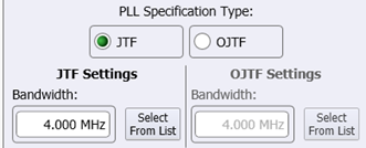
First Order Settings
When you select a First order PLL Loop, you'll need to enter the bandwidth for both the JTF and OJTF curves.
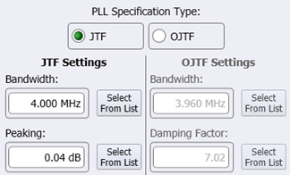
Second Order Settings
When you select a Second order PLL Loop, you'll need to enter the JTF settings for Bandwidth and Peaking and OJTF settings for Bandwidth and Damping Factor.
Third Order Settings
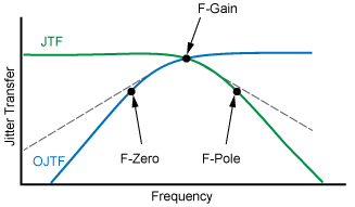
When you select a Third order PLL Loop, you'll need to enter settings for F-Gain, F-Pole, and F-Zero. F-Gain sets the approximate loop bandwidth of the PLL. F-Pole sets the frequency at which the JTF starts to roll-off at 40 dB/decade. F-Zero sets the frequency at which the OJTF starts to roll-off at 40 dB/decade.
with Zero, Pole, and Gain Frequencies