Optical Channel Setup (FlexRT)
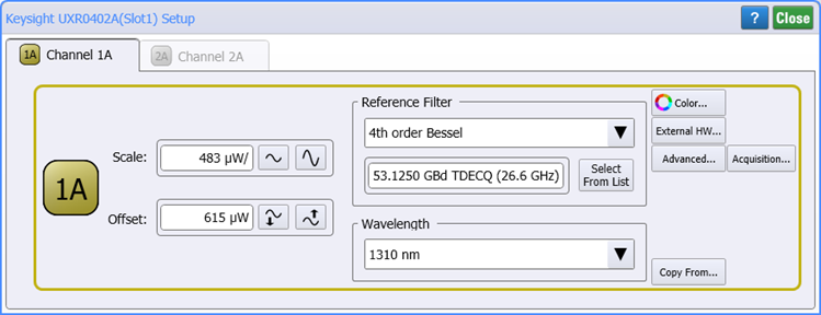
Use the Keysight UXR040X Setup dialog to properly view and vertically scale an Infiniium UXR oscilloscope's waveform on FlexRT's display.
To open this dialog, click Setup > Module > UXR040X: Channels....
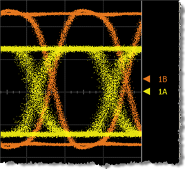
 Click the channel button to display or hide the channel's waveform on the display.
Scale sets the channel's sensitivity (Watts-per-division), with vertical expansion and contraction about the second graticule division from the bottom of the display screen.
 Offset sets the waveforms vertical position. The waveform is identified by a ground marker (
 ). This marker is located on the display's right side, has the same color as the associated waveform, and identifies the location of 0W. Each channel has its own ground marker. The default marker position is two graticules down from the middle screen for optical channels. During an Auto Scale, an offset is applied to vertically center the signal. The offset changes the vertical position of the waveform on the display screen without modifying the waveform itself. The offset value represents an absolute value on the instrument display. The amount of offset applied is shown on the Channel button. You can also quickly change a waveform's vertical offset by using the pointing device to vertically drag the ground marker ( ) on the display.
Reference Filters
Reference Filters are used with optical channels for compliance testing. For example, SONET/SDH, Gigabit Ethernet, and Fibre Channel standards have defined the compliance tests for consistency in standard measurements. These tests must be performed in a specific bandwidth. This bandwidth is achieved using the filters in the optical channels. The compliance tests then verify the performance of the input signal in that bandwidth. These filters concur with specific SONET/SDH, FC, or Gb En symbol rates.
Reference filter selections in the drop-down list include a value in parenthesis that represents the nominal system bandwidth (O/E amplifiers, samplers, and A/D conversion) for a chosen hardware filter.
For TDEC compliance measurements, the relevant standard calls for a specific reference filter to be used. Select the TDEC (12.6 GHz) filter in the Reference Filter drop-down list. This reference filter is not required unless you are performing a compliance measurement.
Wavelength Setting
Use the Wavelength field to select the calibrated wavelength for measurements. Optical channels use an internal photo detector to receive an optical signal and then convert this signal to an electrical signal. A conversion gain (factor) is used to accurately display the signal in optical power units. For example, 1 mW of optical power yields a 28 mV electrical signal. Optical channels are factory calibrated at a specific Wavelength to provide both accurate display of the received optical waveform in optical power units and measurement of the signal's average power.
- Refer to Optical Calibration to learn the calibrated wavelengths of individual modules. Optical channels have reduced bandwidth settings for improved noise performance.
Custom Waveform User Names
Waveforms displayed in tiled, stacked, or zoom tiled views include a waveform label. You can change the waveform's labels to your own more meaningful user name by clicking on the label in this dialog.
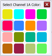
Waveform Color

Click the Color button to display the waveform in one of 16 colors.
External Hardware Scaling

Click External HW to compensate for an external transducer or external attenuator in the test setup. External hardware scaling is available for both electrical and optical channels.
Advanced Settings

Click the Advanced to select the channel's Sampler Bandwidth, enter Horizontal Software Delay, and to select the signal type: NRZ or PAM4.
Acquisition Settings

Use FlexRT's Configure Channel Acquisition dialog to override, for the selected channel, universal settings that configure how FlexRT interpolates and samples the channel waveform.
Optical Wavelength Regions
The following tables show wavelength bands and regions commonly used in the optical communications industry. The band and region ranges are listed for classification purposes, and do not necessarily imply specification of a given range.
| Wavelength Band | Range |
|---|---|
| region II | 1260 nm to 1360 nm |
| region IIe | 1360 nm to 1480 nm |
| S-band | 1440 nm to 1530 nm |
| C-band | 1530 nm to 1565 nm |
| L-band | 1565 nm to 1625 nm |
| M-band | 1625 nm to 1675 nm |
| Wavelength Band | Range |
|---|---|
| region Im | 770 nm to 910 nm |
| region IIm | 1260 nm to 1380 nm |
Copy From

Click Copy From to import the following settings from another channel:
- Scale
- Offset
- Software Delay
- Signal Type Auto Detect and Type
- External Transducer settings
- External Attenuator settings
The copied settings do not include waveform color or any custom waveform name.