Tracking Markers
Tracking Markers
Tracking markers measure the position and magnitude at any sample point on a single-valued waveform. Tracking markers can be placed on Waveform, Freq-Mag, Phase, GrpDelay, Time-Ohms, Time-Volts, and Time-% waveform content windows. When a tracking marker is placed on a Freq-Mag, Phase, and GrpDelay window, it appears on the same x position on all three of these windows. In TDR mode, a tracking marker assigned to a Time-Ohms, Time-Volts, and Time-% window does not appear on the other Time windows. Freq-Mag, Phase, and GrpDelay windows are displayed for TDR Mode's S-parameters and when using the FFT math function (other than an FFT that is defined as Linear Magnitude). Time-Ohms, Time-Volts, and Time-% windows are displayed for TDR Mode's T-parameters.
Phase For multi-valued waveforms, like eye diagrams, use manual line markers.
In Oscilloscope Mode, turn pattern lock on if a multi-valued waveform is displayed.
In Eye/Mask Mode:
- Turn Pattern lock on
- If Acquire Entire Pattern is selected, turn Wrap Waveform off.
In TDR/TDT Mode, assign the marker to a channel, T-domain, or S-parameter waveform.
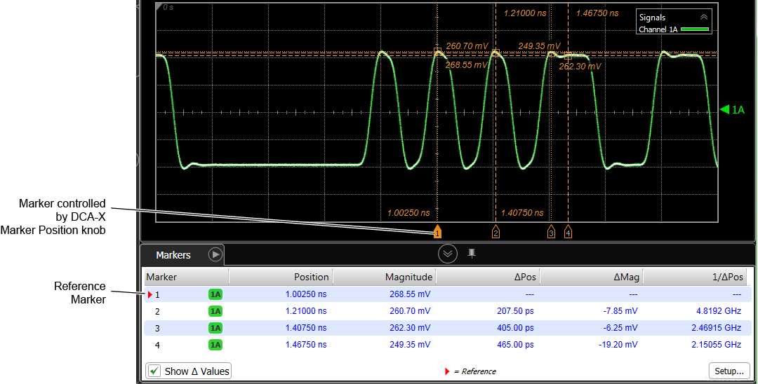
If multiple waveforms are displayed, you can assign the marker to a Source Waveform. In TDR mode, channels are labeled by DUT and Port number. For example, marker 1 in the above picture is assigned to DUT 1 Port1 (1A), which is channel 1A. Also notice in the picture that marker 2 is assigned to T-domain response T11, which is displayed in a Time-Volts waveform content window.
| Source Type | Valid Source Waveforms |
|---|---|
| Waveform | Channels, or T-domain responses (TDR mode) |
| S-Parameter (TDR mode) | S-Parameters |
To Turn on Tracking Markers
- Click Measure > Markers to open the Markers dialog (shown above), and select the Tracking Markers tab. In the dialog, click one of the four available tracking marker button so that it turns green. The marker is now turned on. Select the Source Waveform on which to place the marker.
- Click the quick access toolbar button.

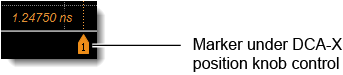
- On an DCA-X, press the front-panel Marker Position knob. If multiple markers are turned on, pressing this knob selects different markers. The marker under Marker Position knob control are displayed using a solid marker handle:

You can simultaneously use both tracking markers and manual line markers on Waveform content windows (non-spectral graphs). However, turning on a tracking marker disables the associated manual line markers. For example, turning on tracking marker 2 disables manual markers X2 and Y2.

 On a DCA-X, you can move markers by turning the front-panel Marker Position knob. When multiple markers are displayed, pressing the Marker Position knob selects the active marker for positioning with the front panel knob. The displayed marker handle turns solid, instead of an outline, indicating the marker is assigned to the position knob. Repeatedly press the Marker Position knob to move through all active markers. You can also simply drag the marker line or marker handle that is shown on the display. Depending on the display window view, the marker handle may not be visible. For exact marker positioning, enter the marker value directly in the Markers dialog.

 Click to select the tracking marker. Tracking markers are designed for single-valued waveforms which can be displayed in Oscilloscope Mode or in Eye/Mask mode (pattern-lock trigger, Acquire Entire Pattern selected, and Wrap Waveform cleared). Waveform tracking markers track the waveform at the position determined by the X-axis marker. A small box appears at the intersection of the X and Y markers. This box moves along the waveform as you reposition the X-axis marker on the display graticule. When using waveform tracking, the manual markers are unavailable. Waveform tracking is disabled and manual marker mode is enabled when the Y-axis marker is turned on.
Reference Marker and Markers Table
When multiple markers are turned on, you can measure the time and magnitude difference between any two waveform locations. The first marker becomes the reference marker, and the position of all subsequent markers is measured relative to the location of the reference marker. As shown in the above picture, the reference marker is identified in the Marker table by a red triangle  . To show or hide the Δ Pos (delta position), Δ Mag (delta magnitude), and 1/Δ Pos (reciprocal of delta position) values in the Markers table, click Show Δ Values. Click Setup to open the Markers dialog.
To change the reference marker:
- Use the dialog's Reference Marker drop-down selection, or
- In the Markers table, click the marker entry beneath the Marker heading.
Marker values are based on the units of the source waveform. The marker resolution is limited to the resolution of the display.
If you adjust the waveform's horizontal position, the markers will move with the waveform, and the marked position value does not change, even if the marker is moved off the screen.
The marker buttons are also enabled whenever Histogram Windowing or Mask Test Scaling is enabled. You can then use the marker knobs to adjust the marker lines.
Markers and Waveform Sampling Points
When positioning a tracking marker between waveform sampling points, the marker's time position and associated y-axis value may be restricted. For non-spectral waveforms this is determined by Pattern Lock's Acquire Entire Pattern setting as described in the following table. Because there is normally an abundance of waveform sampling points on screen, you may seldom notice that a marker is restricted to specific positions and values.
| Acquire Entire Pattern Setting | Marker X-Axis Position | Marker Y-Axis Value |
|---|---|---|
| Non-Spectral Waveforms | ||
| Enabled | any time position | interpolated |
| Disabled | restricted to sampling- point position |
nearest sampling- point value |
| Spectral Waveforms (such as created by the FFT function) | ||
| Enabled | always restricted to sampling-point position | always nearest sampling-point value |
| Disabled | ||
To observe markers restricted to sampling points:
- Switch to oscilloscope mode and select single-sweeps.
- Open the Waveform tab of the Acquisition dialog, and set the Samples/Waveform setting to 16 sample points.
- Open the Display Setup dialog and turn the Connect Waveform Points setting off.
- Drag the tracking marker using the marker handle, and you will see that the marker can only be positioned on sampling points. You can also click the position arrows in the dialog. If you enter a specific marker position in the dialog's Position field, the marker will move to the entered location but the amplitude value will be equal to the amplitude at the nearest sampling point.