FFT Operator
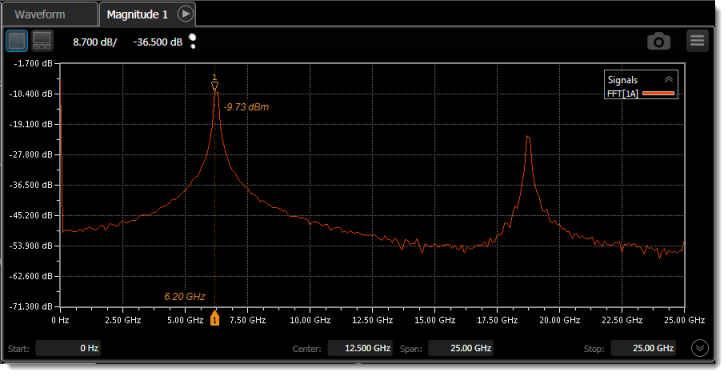
![]() The Fast Fourier Transform (FFT) function takes the sample points of the waveform in the time domain and computes the frequency components. The FFT operator is not available in Jitter mode.
The Fast Fourier Transform (FFT) function takes the sample points of the waveform in the time domain and computes the frequency components. The FFT operator is not available in Jitter mode.
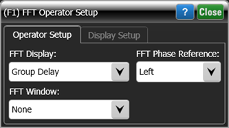
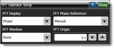 After placing the function, click on the function icon to open the dialog shown here. Select to display the FFT to be one of the types that is listed in the following table.
| FFT Display | Shown in Waveform Content Window |
|---|---|
| Linear Magnitude | Waveform |
| dBV | Freq-Mag |
| dBm | Freq-Mag |
| dB (Normalized) | Freq-Mag |
| Phase | Phase |
| Unwrapped Phase | Phase |
| Group Delay | GrpDelay |
If Phase, Unwrapped Phase, or Group Delay is selected, the FFT Phase Reference field is displayed, which you can define to be Left, Right, or Manual. Selecting Manual to enter the FFT Origin in seconds. Regardless of the type off FFT Display selected, you can select that a Hanning FFT Window be applied. If the input is an optical signal and dBV (Electrical) is selected, the Voltage Conversion Factor field is displayed, which allows you to enter a voltage conversion factor (V/W).
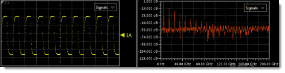
To ensure that enough data is available to construct a useful FFT, set FlexDCA's timebase scale equal to the waveform's period. This will display 10 waveform cycles. For example, for a 5 GHz (200 ps) reference clock, enter a scale setting of 200 ps/division.
Tracking marker pairs cannot be positioned between the graph's data points. This will become noticeable as the graph's span is reduced. Dragging the marker label  or clicking the position arrows in the Marker's dialog always results in the marker being placed on a data point. If, however, you enter a specific marker position in the dialog's Position field that is not at a data point, the marker will move to the entered frequency location but the amplitude value will be equal to the amplitude at the nearest sampling point.
Content Windows
The FFT waveform is automatically displayed in the appropriate type of content window, which is listed in the following table.
Under remote control, additional content windows of the same type are available which you can optionally move the waveform to using the :FUNCtion{1:16}:CWINDdow command.
When you display the FFT as a Linear Magnitude, the waveform is displayed in a Waveform waveform content window. To view the FFT waveform, turn on pattern lock so that a single-valued waveform is provided as the function's input. In Eye mode, if the entire pattern is acquired, additionally turn waveform wrapping off.
| FFT Display Selection |
Displayed Content Window |
Number of Available Windows |
Scale Units | |
|---|---|---|---|---|
| Via Front Panel |
Programmatically | |||
| Linear Magnitude | Waveform | 1 | 1 | Y-Axis: Volts or Watts (linear scale) X-Axis: seconds |
| dBV | Freq-Mag | 1 | 4 | Y-Axis: dB (logarithmic scale) X-Axis: Hertz |
| dBm | ||||
| dB (Normalized) | ||||
| Phase | Phase | 1 | 4 | Y-Axis: phase (°) X-Axis: Hertz |
| Unwrapped Phase | ||||
| Group Delay | GrpDelay | 1 | 4 | Y-Axis: seconds X-Axis: Hertz |
The operator's Display Setup configures the manner in which the resulting waveform is displayed including both vertical and horizontal scaling. Track selection to allows the output waveform to track changes to the scaling of the input waveform. Track is the default setting. In addition, you can turn the waveform's display off or on and select the color of the trace.
Use the Name button to give the displayed waveform a custom identifying name which is show in the Signals area on the display graticule and in the Signals palette. Custom names are very helpful for screen captures or when multiple waveforms are displayed.
The Graph Window is available when multiple waveform content windows are used.
Use the Signal Type's Track selection to allows the waveform type (NRZ or PAM4) to track the input waveform's type. Track is the default setting. If input waveform's type cannot be automatically determined, select Manual to specify the waveform type.