Oscilloscope Mode Quick Start

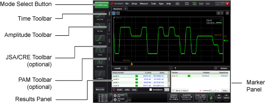
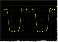
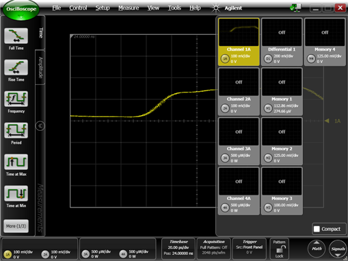
Use Oscilloscope mode to make measurements on pulse waveforms, such as the clock signal shown here. Oscilloscope measurements are designed for single-valued waveforms and only work when a single-valued waveform (not an eye diagram) is displayed on the screen. This is in contrast to Eye/Mask mode, where measurements require a measurement database, to which histograms and statistically-based measurements are applied. In Oscilloscope mode, measurement results are calculated from the most recent acquisition record of the active channel. For each record, the instrument must be triggered by an external signal and for each trigger event, one data point is captured.
Viewing Repetitive, Random Signals
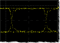
In Oscilloscope mode, repetitive, random signals result in a displayed eye-diagram, as for example the PRBS signal shown here. Oscilloscope mode measurements can not be made on this displayed waveform. If a pattern trigger is provided, this signal can be acquired and displayed as a single-valued waveform. If the instrument has Option PLK (Pattern Lock) installed, use automatic pattern lock to view this signal as described in the following procedure. Otherwise, you must provide a pattern trigger.
Procedure
- If you are using an N1000A,
- Select a module that is compatible with the type of signal that you are measuring.
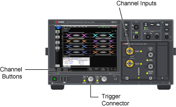
- Use a cable to connect the data signal to the module's front-panel channel input connector. Connect a synchronous clock signal to the front-panel Trigger input connector. You can use a divided clock signal (clock rate/N). If you don't have a synchronous clock signal, install and setup a clock recovery module.
- If you are using an N109x-series DCA-M scope,
- Use a signal that is compatible with the DCA-M model.
- Use a cable to connect the data signal to the module's front-panel channel input connector. Connect a synchronous clock signal to the front-panel Clock In connector. You can use a divided clock signal (clock rate/N). Additional information on connecting a DCA-M scope. If you don't have a synchronous clock signal, install and setup a clock recovery module.
- Start FlexDCA.
- Click Setup > Default Setup to place the instrument in a known start-up state.
- Click the Signals button that is located in FlexDCA's lower, right corner to open the Signals palette.
- On the Signals palette, click the channel button,
 ,to select the module input channel that you are using. The channel button's color changes from gray when the channel is selected. This example shows Channel 1A displayed. Click the Signals button again to collapse the Signals palette.
 - Click the Trigger button to open the Trigger Setup dialog. Or, click Setup > Trigger Setup.
- On the dialog, select the General Trigger Setup tab.
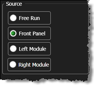
- In the Source: field, select Front Panel.
- On an N1000A, for the Trigger Bandwidth, select:
- Edge Trigger (DC–2.5 GHz) if the trigger rate is below 3.2 GHz (not 3.2 GBd)
- Clock Trigger (50 MHz – 32 GHz) if the instrument has the enhanced trigger installed (Option PLK) and the trigger rate (or divided trigger rate) is between 3 GHz and 32 GHz.
-
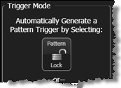
 If you are attempting to measure a repetitive, random signal (such as a PRBS signal shown here), you must establish pattern triggering. In the dialog, click the Pattern Lock button to turn Pattern Lock from off
  to on
to on  . (If you view a random signal without Pattern Lock lock, the waveform will appear as an eye diagram; oscilloscope measurements cannot be made on the waveform.)
 - Close the Trigger dialog.
- Click Auto Scale on the menu bar to properly scale the signal.
- To enter Oscilloscope mode, use the mode select button (upper left corner), or click Setup > Mode > Oscilloscope.
- On the toolbar, select one of the available measurements. The measurement results are displayed in the Results panel.
-
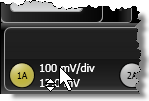 To manually adjust waveform scaling:
 - Scroll-Wheel Mouse. The mouse pointer changes to this shape
 when it is placed over the scaling labels on a channel button, trigger button, or in the waveform Signal palette. Turn the mouse wheel to adjust the scale and offset setting.
 - Click a channel, trigger, or waveform Signal palette button to make these adjustments using a dialog.
- If FlexDCA is running on the instrument, turn the front-panel horizontal and vertical adjustment knobs.

If you accidentally click to the right of the button, a dialog opens for scaling the displayed waveform. Close the scaling dialog.

Pattern Lock requires an N1000A-PLK or N109x-PLK DCA-M instrument option.
