Quick Start
Quick Start
To view a signal on the DCA-X
The DCA-X are equivalent-time sampling oscilloscopes that can simultaneously measure a variety of high speed digital communication waveforms from 50 MBd to over 80 GBd on up to 16 channels.
- Press the Default Setup button on the DCA-X's front panel. A Default Setup configures the instrument in a known startup condition including:
- Oscilloscope mode
- Front Panel triggering
- Displays Channel A on the lowest numbered occupied slot for display. All other channel inputs turned off. For example if an N1045A module is installed in slot 3 and a DCA-M is installed in slot 6, Channel 3A will be the only displayed channel.
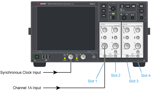
- Connect a signal to a front-panel channel input. In this example, the signal is connected to Channel 1A, since Default Setup will automatically select Channel 1A. Channel inputs are located on the front-panel of plug-in modules.
- Connect an external synchronous clock to the front-panel Trigger Input connector. The trigger signal must be a clock that is synchronous to the input signal or a pulse that indicates when the signal repeats.
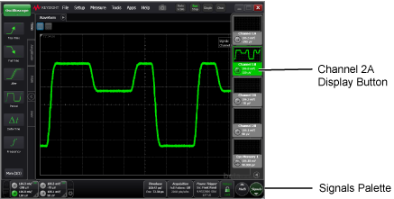
- If the signal is not connected to Channel 1A, click the Signals button, located in the lower-right corner of the display, to open the Signals Palette. On the palette, click channel buttons to turn the display of various channels on and off. The Signals Palette shows all available channels, simulated channels, functions, and memories. Select the channel that you want to view and close the Signals Palette. Note that in this picture, pattern lock was turned on so that the PAM4 waveform is properly displayed.
- Press the DCA-X's front panel Auto Scale button.
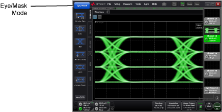
- If the signal resembles an eye diagram as shown in the above picture, change the instrument mode to Eye/Mask. In the display's upper left corner, click the mode button and select Eye/Mask mode. Oscilloscope mode is designed for viewing single-values waveforms such as pattern waveforms. Eye/Mask mode is designed for multi-valued waveforms such as eye diagrams.


You can also provide a trigger using a hardware clock recovery module. When the trigger edge transitions through a predefined threshold (typically on the rising edge), the oscilloscope starts sampling and acquiring signal data and then reconstructs the waveform to display it on the screen.
Instrument Modes
The instrument can be placed in one of four instrument modes as listed in the following table.
| Mode | Quick Start |
|---|---|
| Oscilloscope Mode for single-valued waveforms. | Quick Start |
| Eye/Mask Mode for eye diagram analysis and standards testing (for example, SONET/SDH, Gigabit Ethernet, and Fiber Channel). | Quick Start |
| Jitter/Amplitude Analysis Mode. Requires N1000A-PLK Pattern Lock with Research and Developement license (RND). | Quick Start |
| TDR/TDT Mode for time domain reflectometry measurements. |
The DCA-X's graphical user interface is known as FlexDCA, and it is important to understand the different ways in which the DCA-X and FlexDCA can be used.
For optimum measurement results, allow the temperature of the instrument to stabilize after applying power.
Oscilloscopes respond to trigger signals in different ways, depending on their architecture. Real-time oscilloscopes use a traditional oscilloscope architecture. The DCA-X uses an equivalent-time sampling architecture to acquire and display wide bandwidth waveforms. The following sections explain both the real-time and the equivalent-time sampling architectures.