Jitter Mode Quick Start
Quick Start
 Jitter Mode allows you to quickly measure and troubleshoot the components of jitter. Measurements can be made on optical or electrical input NRZ or PAM4 data using all existing DCA modules. Practice viewing a PRBS signal, which will have a varied number of ones and zeros and will produce a classic eye diagram.
- If you are using an N1000A,
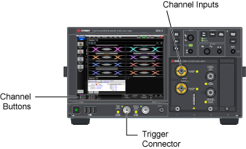
- Select a module that is compatible with the type of signal that you are measuring.
- Use a cable to connect the data signal to the module's front-panel channel input connector. Connect a synchronous clock signal to the front-panel Trigger input connector. You can use a divided clock signal (clock rate/N). If you don't have a synchronous clock signal, install and setup a clock recovery module.
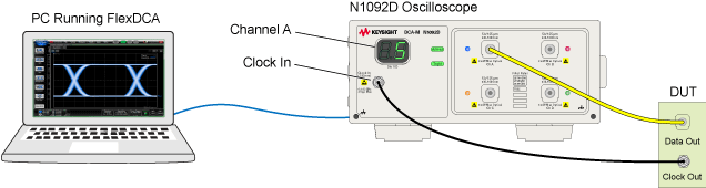
- If you are using an N109x-series DCA-M scope,
- Use a signal that is compatible with the DCA-M model.
- Use a cable to connect the data signal to the module's front-panel channel input connector. Connect a synchronous clock signal to the front-panel Clock In connector. You can use a divided clock signal (clock rate/N). Additional information on connecting a DCA-M scope. If you don't have a synchronous clock signal, install and setup a clock recovery module.
- Start FlexDCA.
- Click Setup > Default Setup to place the instrument in a known start-up state.
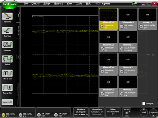
- Click the Signals button that is located in FlexDCA's lower, right corner to open the Signals palette.
- On the Signals palette, click the channel button,
 ,to select the module input channel that you are using. The channel button's color changes from gray when the channel is selected. This example shows Channel 1A displayed. Click the Signals button again to collapse the Signals palette.
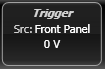
 - Click the Trigger button to open the Trigger Setup dialog. Or, click Setup > Trigger Setup.
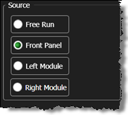
- On the dialog, select the General Trigger Setup tab.
- In the Source: field, select Front Panel. If you are using a clock recovery module with an N1000A-PLK instrument, select Left Module or Right Module to use the recovered clock.
- On an N1000A, for the Trigger Bandwidth, select:
- Edge Trigger (DC–2.5 GHz) if the trigger rate is below 3.2 GHz (not 3.2 GBd)
- Clock Trigger (50 MHz – 32 GHz) if the instrument has the enhanced trigger installed (Option PLK) and the trigger rate (or divided trigger rate) is between 3 GHz and 32 GHz.
- Close the Trigger dialog.
- Click Auto Scale on the menu bar to properly scale and display the signal.
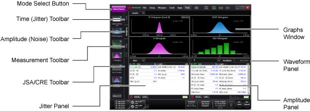
- To enter Jitter mode, use the mode select button (upper left corner), or click Setup > Mode > Jitter/Noise. Jitter graphs are displayed and default measurement results are results in the Jitter panel. Use the toolbars to select additional graphs and measurements.
If you accidentally click to the right of the button, a dialog opens for scaling the displayed waveform. Close the scaling dialog.