Configuring Simulated Modules
Use the Configure Simulation Source dialog to configure a simulated waveform.
In this dialog:
- Click the Data Source block to select the waveform type and symbol rate.
- Click the Filter block to add filtering.
- Click the Jitter & Noise block to add jitter and noise.
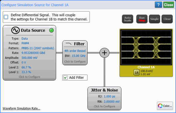
The average power measurement can not be made on simulated optical channels.
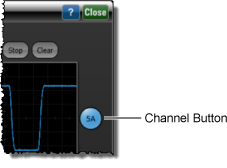
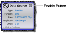
To Display a Simulated Waveform
- Click the channel button so that it shows the color assigned to the waveform.
- Click the Enable button to turn on the waveform.
- If the Filter block is not displayed in this dialog, select Add Filter. After configuring your simulated waveform, you can quickly turn the channels on and off using the Signals palette, channel buttons, or by clicking Setup > Modules > Channel X.
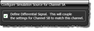
Differential Electrical Signals
When configuring Channel B on a simulated dual-electrical module, the additional Define Differential Signal checkbox will be displayed, as shown in this picture. Select this checkbox if you want channel A and B to be differential. All changes that you enter for waveform A will be automatically entered for waveform B.
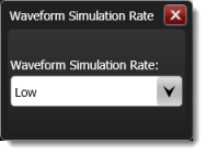
Waveform Simulation Rate

Click Waveform Simulation Rate in the lower-left corner of the dialog to open the Waveform Simulation Rate dialog which selects the amount of CPU usage devoted to data simulation: Low, Standard, or High. The default setting is Standard. Adjusting this setting can affect the performance of FlexDCA and any concurrently running applications.
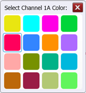
Waveform Color
Click the Color button to display the waveform in one of 16 colors.