Timebase Setup
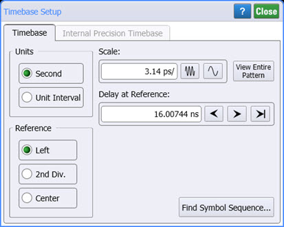
Use the Timebase Setup dialog to select the horizontal units and reference position and to adjust the horizontal scale. You can select either seconds or Unit Interval (UI) displayed for horizontal scale and position.
When you click Auto Scale on the menu bar, FlexDCA adjusts the horizontal scale based on the trigger source and input selected. The waveform is evaluated and adjusted so that at least one cycle (or edge) of the waveform is displayed (within 6 horizontal graticule divisions).
Units
The horizontal units can be set to either seconds or Unit Interval (UI). Clicking the range buttons increases or decreases the scale in a 1-2-5 sequence; the waveform width will compress. The 1-2-5 sequence gives FlexDCA the ability to assign whole, easy to interpret values. For example, the scaling can change from 10 ns/div to 20 ns/div and from 20 ns/div to 50 ns/div.
If pattern lock is on, click View Entire Pattern to automatically set the scale for the pattern length. The View Entire Pattern button not visible when Pattern Lock is off.
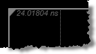
Delay at Reference. Increase or decrease the delay from reference horizontal position. This sets the delay between the time a trigger is received and when the data is actually sampled and is defined relative to the horizontal reference position as described below. As the delay increases, the waveform moves to the left on the display. As the delay decreases, the waveform moves to the right on the display. By default, Reference Left is selected and the Delay at Reference value is displayed in the upper-left corner of the graticule window as shown in the following figure. If Reference Center is selected, the Delay at Reference value is displayed in the upper-center area of the graticule.
 Click the minimum delay button to return the horizontal position to the minimum value. This does not return the position to 0. The minimum value you can set the horizontal position to is 10 ns for an N1000A or the equivalent number or symbols, defined at the left edge of the display graticule. If pattern lock is on (requires N1000A-PLK, or N109x-series DCA-M PLK), the minimum time delay is set by the Minimum Timebase Position setting on the Advanced Trigger Setup tab of the Trigger Setup dialog.
Symbol Rate Selections
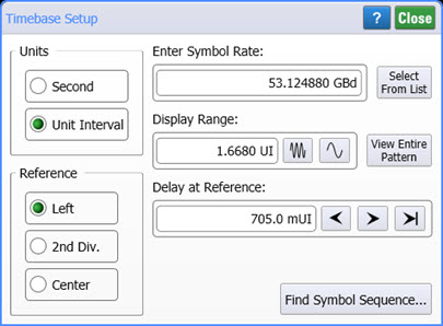 When Unit Interval is selected for the units, the Select From List button is displayed from which you can select from a list of standard optical and digital telecommunications rates. This list is also available in the Pattern Lock Setup tab of the Trigger dialog. To enter a non-standard symbol rate, click the Enter Symbol Rate field. An example of a non-standard symbol rate is 1.36 GBd.
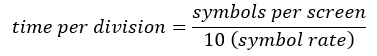
When Seconds is selected as the units, the instrument internally performs the calculation to convert the number of sybols displayed on the screen to the time per division. For example, if you wanted to convert x symbols-per-screen to time-per-division, you would have to compute the following:
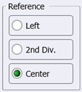
Reference Point
You can set the reference point (an arrow at the top of the display) to the left edge or center of the graticule. The horizontal reference point defines a specific delay value relative to the trigger event. Using the reference point and the horizontal scale, you can view any data point on the screen and determine when the data point was sampled, relative to the trigger event.
Find Bit Sequence
Click Find Symbol Sequence to locate a specific sequence of symbols within a pattern waveform.