Internal Precision Timebase Setup
A precision timebase provides an alternate the instrument's timebase source (clock) that greatly improves jitter performance and timebase linearity. Sampling is random with the precision timebase and the timing of each random sample is precisely identified. The following precision timebases are available:
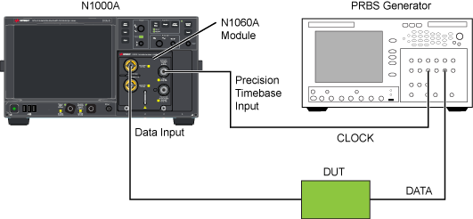
In the following figure, the clock is connected to the N1060A's Precision Timebase Input. In the N1060A Setup dialog's Precision Timebase tab, set the Reference Source to External. In the Trigger Setup dialog's General Trigger Setup tab, set the Source to Automatic. Click Setup > Trigger to open the Trigger Setup dialog.
Figure. Setup for Internal Precision Timebase with N1060A

Avoid damaging the front-panel Precision Timebase Input. Do not use a reference clock greater than ±2V (16 dBm) maximum.
When using a precision timebase, observing the following requirements:
- Connect a full or sub-rate reference clock that is synchronous with the input signal to the front-panel Precision Timebase Input as shown in the above figure. The location of this connector depends upon the precision timebase that you are using.
- If pattern lock will be turned on or Jitter Mode will be used, connect the reference clock to both the Precision Timebase Input and to the front-panel Trigger Input.
- The clock frequency must be entered in the Precision Timebase dialog. The entered frequency value must equal the actual clock frequency with a precision better than 0.1%. Larger differences will affect time accuracy. The inaccuracy is proportional to the error. If the reference clock is turned off or the values for the input clock and specified frequency differ, Auto Scale will fail.
In addition, if you are using an N1000A-PTB or an 86107A precision timebase module, observe the following constraint that when also using a front-panel Clock/Divided trigger without pattern locking the:
N1000A Front-Panel Triger Input Clock Frequency ≤ Precision Timebase Clock Frequency
Failure to comply with these conditions may result in an inaccurately displayed waveform. Also, when pattern lock is turned on, this issue does not occur.
If present, the Internal Precision Timebase (N1000A-PTB) is disabled whenever an 86108A/B Precision Waveform Analyzer Module or 86107A Precision Timebase Module is installed.
Features Affected by Precision Timebase
Auto Scale for Time Reference Only
Auto Scale is one method to reset the time reference. Since the instrument does not use a trigger when the precision timebase is enabled, the internal trigger settings are not affected. Alternatively during Auto Scale, the instrument analyzes the reference clock frequency and resets the time reference in lieu of the trigger.
If the instrument is not able to correctly detect an external clock source during an Auto Scale (resulting in errors), clear Auto Detect so that it is no longer selected. Auto Detect allows the automatic detection whenever an Auto Scale is performed or pattern lock is turned on.
Horizontal Controls
There are different limits on the timebase controls when you enable the precision timebase. These limits are based on the reference clock frequency. The limits on the horizontal scale/division depend upon the maximum and minimum allowable reference clock frequencies. The scale/division limits allow a range of 0.1 period of the maximum frequency to four periods of the minimum frequency on the display screen. For example, if you use the maximum reference clock frequency of 40 GHz, the minimum scale/division is 200 fs/division. Conversely, a minimum reference clock frequency of 9 GHz results in the maximum scale/division of 50 ps/division. For an N1000A, the minimum symbol delay is 10 ns times the selected symbol rate. The maximum symbol delay is equal to the minimum delay plus the number of symbols in two periods of the reference clock.
If you select Unit Interval (UI) as the units for horizontal scale, the minimum symbol rate you can select is the frequency of the reference clock. The symbol rate value is restricted to multiples of the reference clock frequency. For example, if you have set up a reference clock of 10 GHz, your symbol rates can be 10, 20, or 40 GBd.
The number of UIs that can be displayed is also limited. You can enter a value from 0.1 to 16 UIs. The maximum value allows the instrument to display up to four periods of the reference clock, when the symbol rate is four times the reference clock frequency.
Horizontal Skew in Precision Timebase
When you enable the precision timebase, you can use horizontal skew to adjust the time reference of the waveform. This allows you to line up input channels on the instrument display. You can then establish any point within the symbol period as the time reference. The default skew value for each channel is 0.0s.
Limited Trigger Controls
When you enable the precision timebase, you can view the signal's amplitude without a traditional trigger source. The instrument disables all other trigger sources and controls.
Precision timebase modules provide internal filtering for reference clock signals in certain frequency bands. Within these bands, you may use a typical digital clock signal. For example, a square wave, BERT output, or a sine wave. Outside of these bands, external filtering may be required to provide a clean sine wave for the reference clock. If the reference clock signal varies from a sinusoid, there will be error in the precision of the timebase. Thus harmonics and subharmonics should be eliminated.
To ensure accuracy, you must set the reference clock frequency and the external reference clock to the same frequency. Any deviations in either frequency will result in an inaccurate timebase. The instrument will display a warning message on the screen if the time reference is not valid. You must ensure that you connect a valid reference clock.