N1060A / 86107A Precision Timebase Setup
Precision Timebase Module Setup
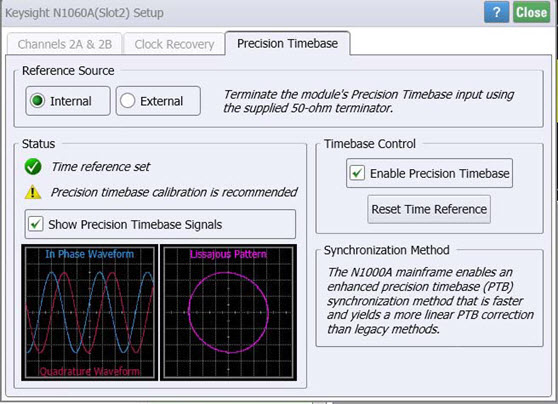
Use the N1060A or 86107A Precision Timebase Setup dialog to configure and turn on the module's precision timebase. The module has a front-panel port to connect an external clock.

If the dialog displays the message Precision timebase calibration is recommended as shown in the above picture, click the menu commands Tools > Calibrations to locate and perfomr the calibration.
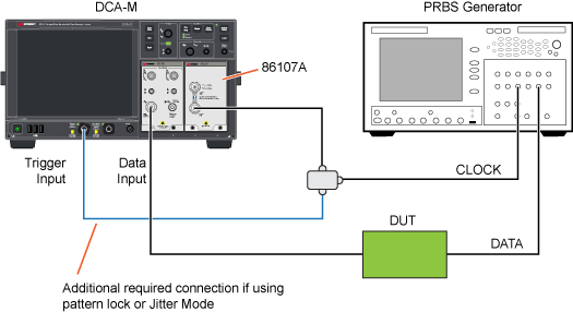
Before entering the data in this dialog, make the required connections as shown in the following figure. When the precision timebase is used, the instrument does not normally use a trigger. The reference clock is connected directly to the module's front-panel Precision Timebase Input. You can also use the 86107A in Free Run mode with this setup.
If pattern lock is turned on or Jitter Mode is used, connect the reference clock to both the module's precision timebase reference clock Input and to the DCA-X's front-panel Trigger Input.
Figure. Setup for 86107A with Pattern Lock or Jitter Mode

Reference Clock Frequency Settings
Select the Reference Clock Frequency by clicking Select From List. This displays a list of standard optical and digital telecommunications rates. This list is also available in the Pattern Lock Setup tab of the Trigger dialog. FlexDCA determines the phase of a data sample within one period.
If pattern lock is turned on, the Autodetect check box is displayed as shown in this picture. An Auto Scale automatically detects the external reference frequency. With pattern lock on, the instrument may be unable to correctly detect an external reference frequency. If this happens, clear the Autodetect check box.
PRBS data is not a suitable reference clock signal.
To ensure accuracy, the entered reference clock frequency must equal the actual external reference clock. Any deviations in either frequency will result in an inaccurate timebase. The instrument will display a warning message on the screen if the time reference is not valid. You must ensure that you connect a valid reference clock. If the precision timebase is on, you can perform an Auto Scale to reset the time reference.
Within the frequency bands listed in the following table, the reference clock input to the 86107A module can be a typical digital clock signal: square wave, BERT output, or a sine wave. Outside of the listed bands, a sine wave should be used or an external low-pass filter may be required to provide a clean sine wave for the reference clock. If the reference clock signal varies from a sinusoid, there will be error in the precision of the timebase. Thus harmonics and subharmonics should be eliminated.
| 86107A Input Range | Internal Filtered Bands |
|---|---|
| 86107A-010 (2.0 to 15 GHz) | 2.4 4.0 GHz 9.0 12.6 GHz |
| 86107A-020 (2.4 to 25 GHz) | 9.0 12.6 GHz 18.0 25.0 GHz |
| 86107A-040 (2.4 to 48 GHz) | 9.0 12.6 GHz 18.0 25.0 GHz 39.0 45.0 GHz |
Using 86107A-040. Use only one input connector at a time. If both inputs on the module are connected to external equipment, a significant amount of cross talk will occur, producing invalid results. To avoid invalid results, terminate the unused input (preferred) or leave open (disconnected). If you connect a 10-20 GHz signal to the 40 GHz input, the resultant waveform will appear distorted, non-linear, and the time axis will be inverted.
Observe the following additional clock requirements:
- Frequency range listed above
- 0.5 to 1.5V peak-to-peak amplitude
- Signal to noise ratio: 200:1 or better
- Subharmonic content: < –30dB
- Duty Cycle: 50% (preferred)
- DC Offset range: ±200mV.
- The following blocking capacitor accessories are recommended: Keysight 11742A (86107A-010), Keysight 11742A (86107A-020), and Keysight 11742A-K01 (86107A-040). The 11742A (and 11742A-K01) blocking capacitor prevents DC offset if DC offset is greater than ±200mV.
When using the 86107A, be aware that jitter becomes a system parameter. In other words, the system jitter is dependent upon the specific DCA-X mainframe, vertical channel, and 86107A module used in the measurement. As a result of the interaction between the instrument mainframe and module, the jitter performance cannot be specified. However, statistical data supports that the generated RMS jitter will be in the order of 200 fs.
Use only compatible connectors, adapters and cables to provide the reference clock signal. The input to the 86107A-010 is a 3.5 mm electrical connector. The input to the 86107A-020 is a 3.5 mm electrical connector. The inputs to the 86107A-040 include both a 3.5 mm and a 2.4 mm electrical connector.
Timebase Control Settings
 Select Enable Precision Timebase to enable or disable the precision timebase. The Precision Timebase button's green indicator
  (on the button toolbar) indicates when the precision timebase is on. If the yellow warning indicator
  is shown, the time reference is not set or the signal is not connected to the 86107A's front'panel connector. If any changes in the reference clock occur, click Reset Time Reference to reset the precision timebase. The time reference will fail if:
- Reference clock signal does not meet the requirements listed above
- A setup, in which the precision timebase was enabled when saved, is recalled
- The instrument power is turned on, when the state of the precision timebase is enabled at instrument power off
Synchronization Method Settings

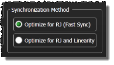
By default, precision timebase synchronization optimizes for RJ (Random Jitter) only. This provides a fast synchronization that is suitable for analysis of most signals. Optionally, you can choose to optimize both for RJ and for timebase linearity. This type of synchronization takes much longer but results in an extremely linear timebase as well as the lowest possible RJ. This type of synchronization is suggested for signals with extremely low DJ (Deterministic Jitter), where the signal rate is a multiple of the precision timebase reference frequency. For example, if your Symbol Rate is 32 GBd while your precision timebase reference frequency is 8 GHz, this option may improve the accuracy of the DJ measurements.
Status
The Status area of the dialog provides the following messages:
- Precision Timebase Off. The precision timebase is disabled. The time reference will be invalid until the precision timebase is enabled.
- No Time Reference. The precision timebase is enabled; however, the time reference is invalid. This status appears after changing the frequency band of the reference clock signal or recalling an instrument setup.
- Time Reference Set. The precision timebase is enabled and the time reference is valid.
- Time Reference Lost. The precision timebase is enabled. The instrument continues to acquire data using the most recent time reference. This status follows an absent reference clock signal, a clock signal that is too large (or too small), a clock signal that is not in a valid frequency band, or a clock signal that does not have a stable frequency.
Select the Show Precision Timebase Signals field to view the In Phase Waveform and Quadrature Waveform inputs to the precision timebase circuitry. Both an amplitude-vs-time chart and a Lissajous Pattern chart are displayed. This feature provides a qualitative view of the inputs. There is no remote command for making this selection. However, you can use the :WAVeform:SOURce command remote command to return the two waveforms.