Step 7. PLL Model Setup
Use the PLL Model Settings dialog to modify the default PLL loop settings used to calculate the displayed Model JTF and Model OJTF plots. You can enter different settings for the Response, Memory 1, Memory 2, Memory 3, and Memory 4.
Click Setup > PLL Model Setup to open this dialog.
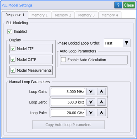
 Select Enabled to display, if selected, the:
-
Model JTF which displays a modeled Jitter Transfer plot.
-
Model OJTF which displays a modeled Observed Jitter Transfer plot.
-
Model Measurements which displays modeled scalar measurements in the results table. The following table lists the measurements included when this setting is cleared versus selected.
| Measurement | Model Measurements Setting |
|
|---|---|---|
|
|
|
|
| Maximum 1 | ■ | ■ |
| Minimum 1 | ■ | ■ |
| Average 1 | ■ | ■ |
| Bandwidth | ■ | ■ |
| Peaking | ■ | ■ |
| Gain Frequency | ■ | |
| Zero Frequency | ■ | |
| Pole Frequency | ■ | |
| Footnotes: | ||
| 1. Displayed if Display Flatness Measurements selected in Memory Setup dialog. | ||
Modeled PLL Loop Definition
Use the Phase Locked Loop Order setting to specify the DUT's PLL order as being First, Second, Third, or Fourth. The loop order that you select is applied to automatically and manually calculated models.
Enable Auto Loop Calculation selects to have FlexPLL automatically calculate the loop parameters based selected loop order. By default, this setting is selected. Clear this setting if you want to base the calculations on your entries in the Manual Loop Parameters fields.
Manual Loop Parameters Fields
When the Enable Auto Calculation is selected, you can click Copy Loop Parameters to copy the FlexPLL's automatically calculated parameters into the Manual Loop Parameters settings. This provides you convenient starting settings for viewing the effects of adjusting the parameters on the displayed model plots.

![]() When the Enable Auto Calculation selection is cleared you can enter custom settings listed in the following table.
When the Enable Auto Calculation selection is cleared you can enter custom settings listed in the following table.
| Loop Parameters | Settings | Description | ||
|---|---|---|---|---|
| Default | Minimum 1 | Maximum | ||
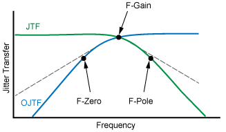
| Gain Frequency | 3.00 MHz | 1 Hz | 1.00 THz | The frequency at which the model JTF and OJTF curves intersect. |
| Zero Frequency | 500 kHz | 1 Hz | 1.00 THz | The single frequency in the JTF model where gain decreases. |
| Pole Frequency | 20.0 GHz | 1 Hz | 1.00 THz | The single frequency in the JTF model where gain increases. |
| Footnotes: | ||||
| 1. A minimum value of 1 Hz prevents the situation where the PLL model has a negative value for the fZero term. | ||||
with Zero, Pole, and Gain Frequencies