Step 1. Connect Hardware
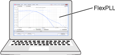
This topic shows examples of how to connect the required test equipment. FlexPLL can be installed to run on a PC or on a DCA-X. The test setup includes a jitter source, jitter receiver, and your PLL based Device Under Test (DUT). Although the drawings show an 81160A as the Source, the setup is the same when using an 81150A, M8000-series BERT, or M8199A AWG.
On FlexPLL and on a DCA-X, click Tools > SCPI Programming Tools > SCPI Server Setup to open the SCPI Server Setup dialog to enable and configure the possible remote control servers.
Valid Jitter Sources for All Setups
- Keysight M8009A clock generator with jitter modulation module (part of the M8050A BERT)
- Keysight M8045A high performance BERT generator-analyzer-clock module (part of the M8040A BERT)
- Keysight M8041A high performance BERT generator-analyzer-clock module (part of the M8020A BERT)
- Keysight 81160A Pulse Function Arbitrary Noise Generator (LAN, USB, or GPIB)
- Keysight 81150A Pulse Function Arbitrary Noise Generator (LAN, USB, or GPIB)
To locate an 81160A's I/O settings, on the 81160A press Utility and then press MORE 1 of 2 > I/O Interfaces > LAN or GPIB Address.
The following test setups show the hardware connected to a LAN, but there are many connection options available in FlexPLL's Source Setup dialog and Receiver Setup dialog. For example, you can connect the DCA-X via the LAN or GPIB and the 81160A via LAN, USB, or GPIB.
The Signal Integrity Package (L-SNG) license must be installed in the DCA-X or PC where you installed FlexPLL.
When connecting the RF cable between the Source's output and the DUT's input, be aware that some PCI Express devices do not include an "on board" termination. In this case, if FlexPLL's default Source amplitude and offset settings are decreased, you may need to connect a 6 dB matching attenuator on the output of the Source.
Example Setup 1. FlexPLL on PC with DCA-X Receiver
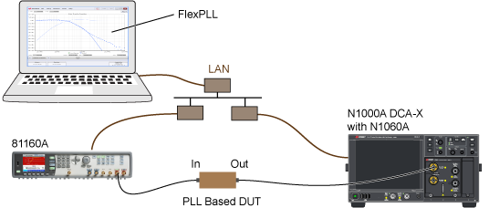
Valid Jitter Receivers for This Setup
- N1000A DCA-X with N1060A Precision Waveform Analyzer module
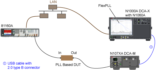
Example Setup 2. FlexPLL on PC with DCA-M Receiver
In this setup, both FlexDCA and FlexPLL must be running on the PC. The N107x-series DCA-M is connected to FlexDCA. In FlexPLL's Receiver Connection Setup dialog, FlexDCA is connected as localhost. In FlexPLL's System Setup dialog's Receiver tab, the DCA CDR Slot field is automatically populated with the FlexDCA slot where the DCA-M is installed.
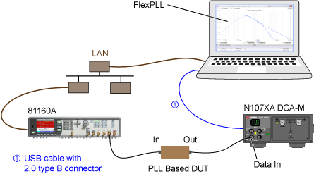
Valid Jitter Receivers for This Setup
- N1076A/B Electrical DCA-M clock recovery module (with option JSA)
- N1077A Electrical (with option JSA)
- N1078A Electrical (with option JSA)
Example Setup 3. FlexPLL on DCA-X Receiver
In this setup, start FlexPLL from FlexDCA's menu by clicking Apps > FlexPLL. FlexPLL automatically connects FlexDCA as the Receiver as localhost. In FlexPLL's System Setup dialog's Receiver tab, the DCA CDR Slot field is automatically populated with the correct FlexDCA slot number. An N1060A module is always shown as installed in slot 1. You can connect an external display to the DCA-X so that you can see both FlexPLL and FlexDCA. Or, if a keyboard is attached, press Alt-Tab to switch between applications.
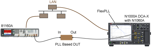
Valid Jitter Receivers for This Setup
- N1000A DCA-X with N1060A Precision Waveform Analyzer module
Example Setup 4. FlexPLL on DCA-X Receiver with DCA-M
In this setup, start FlexPLL from FlexDCA's menu by clicking Apps > FlexPLL. FlexPLL automatically connects FlexDCA as the Receiver as localhost. In FlexPLL's System Setup dialog's Receiver tab, the DCA CDR Slot field is automatically populated with the correct FlexDCA slot number. You can connect an external display to the DCA-X so that you can see both FlexPLL and FlexDCA. Or, if a keyboard is attached, press Alt-Tab to switch between applications.
Valid Jitter Receivers for This Setup
- N1076A/B Electrical DCA-M clock recovery module (with option JSA)
- N1077A Electrical (with option JSA)
- N1078A Electrical (with option JSA)
Example Setup 5. FlexDCA Offline
This test setup allows you to view previously saved JTF response waveforms that are loaded into FlexPLL's response memory. Calibrated response files can be saved to a file during testing and loaded at a latter time into one of four response memories.