JTF & OJTF Concepts
The characteristics of a clock-recovery PLL affect jitter measurements. This is true whether the clock-recovery is part of the DUT or part of a real-time or sampling oscilloscope.
The following figure shows the use of clock recovery to supply a clean clock to a receiver's input signal detection. The input signal is split with one path providing the clock via clock recovery. The phase of the input signal and clock are compared in a sampler. When a clean clock is unavailable, the clock must be recovered and any jitter on the input signal is detected when its phase is compared to that of the recovered clock. For a jitter frequency, the loop bandwidth of the clock recovery PLL affects the ability of jitter on the input signal to be detected.
Simplified Block Diagram of a Clock-Recovery PLL
Jitter Compared: Input Signal Versus Recovered Clock (JTF)
JTF is the graph of a PLL loop's Jitter Transfer Function. JTF, by jitter frequency, compares how much input signal jitter is transferred to the output of a clock-recovery's PLL (recovered clock):
- Input signal jitter that is within the clock recovery PLL's loop bandwidth results in jitter that is faithfully transferred (closed-loop gain) to the clock recovery PLL's output signal. JTF in this situation is approximately 1.
- Input signal jitter that is outside the clock recovery PLL's loop bandwidth results in decreasing jitter (open-loop gain) on the clock recovery PLL's output, because the jitter is filtered out and no longer reaches the PLL's VCO.
Jitter Compared: Input Signal Versus Sampled Signal (OJTF)
OJTF is the graph of Observed Jitter Transfer Function. OJTF compares how much input signal jitter is transferred to the output of a receiver's decision making circuit as effected by a clock recovery's PLL. As the recovered clock is the reference for detecting the input signal:
-
Input signal jitter that is within the clock recovery PLL's loop bandwidth results in jitter on the recovered clock which reduces the amount of jitter that can be detected. The input signal and clock signal are closer in phase.
-
Input signal jitter that is outside the clock recovery PLL's loop bandwidth results in reduced jitter on the recovered clock which increases the amount of jitter that can be detected. The input signal and clock signal are more out of phase. Jitter that is on both the input and clock signals can not detected or is reduced.
PLL Loop Orders
Hardware clock recovery typically uses a second-order loop which has some amount of peaking near the filter cutoff frequency, which increases the jitter spectrum at this frequency. Many standards call out specific characteristics for a clock-recovery PLL. As you can see, jitter measurements are referenced to the clock at the sampler.
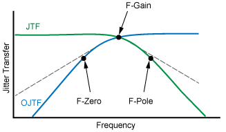
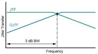
JTF and OJTF for 1st Order PLLs
JTF and OJTF for 2nd Order PLLs
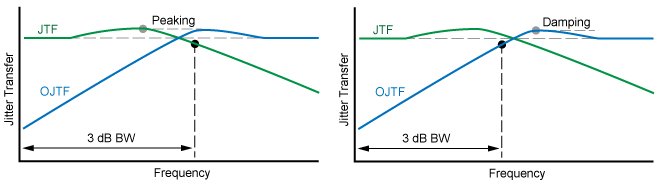
with Zero, Pole, and Gain Frequencies