Parameter Extraction Techniques
This topic provide information on how the PD1500ADouble-Pulse Test software either measures or derives the DPT test data. It also describes some of the differences between the Legacy mode and the IEC 60747 Mode in the PD1500A user interface.
Switching times are defined by IEC standards and are used to measure delay and transition times of power transistors. Switching energies are defined in the same standards.
| Device types | Standard for Discrete Devices | Standard for Power Modules |
|---|---|---|
| IGBT, Enhancement, Si | IEC 60747-9 | IEC 60747-9 |
| FET, Enhancement, Si | IEC 60747-8 | IEC 60747-8 |
| FET, Enhancement, SiC | IEC 60747-8 | IEC 60747-8 |
| FET, Enhancement, GaN, vertical | IEC 60747-8 | IEC 60747-8 |
| FET, Enhancement, GaN, Cascode | IEC 60747-8 | IEC 60747-8 |
| FET, Enhancement, GaN, eHEMT | IEC 60747-8 | IEC 60747-8 |
| FET, Enhancement, GaN, GIT | IEC 60747-8 | IEC 60747-8 |
| FET, Depletion, Si | IEC 60747-8 | IEC 60747-8 |
| FET, Depletion, SiC | IEC 60747-8 | IEC 60747-8 |
| FET, Depletion, GaN, vertical | IEC 60747-8 | IEC 60747-8 |
| FET, Depletion, GaN, Cascode | IEC 60747-8 | IEC 60747-8 |
| FET, Depletion, GaN, eHEMT | IEC 60747-8 | IEC 60747-8 |
| FET, Depletion, GaN, GIT | IEC 60747-8 | IEC 60747-8 |
- FET Turn-On and Turn-Off Characteristics
- IEC 60747-8 Switching Times and Switching Energy
- IEC 60747-9 Switching Times and Switching Energy
- How Gate Charge is Calculated
- Reverse Recovery Characteristics
- Switching Locus
- IV Curve
- Static RON and Dynamic RON
- didt and dvdt
- Output Voltage Peak and Output Current Peak
Additional Parameter Extraction Topics
Ringing
Ringing is cause by the oscillation of voltage or current when electrical signal causes the resonance by inductance and capacitance in a circuit. Often, inductance is regarded as a spring and therefore the most simplified differential equation is represented as d2x/dt2 = -kx. The solution for this is sin (ax). The capacitor works as a source for charge. In the Double-Pulse test circuit, there are parasitic inductances and capacitances as well as the device internal capacitance (mainly CDS of Low-Side FET) contribute to oscillation.
Oscillation or ringing frequency is given by the following equation.equations
where Lp and Cp are parasitics.
Although it is not easy to obtain exact parasitic capacitance and inductance values, this equation is useful to estimate the ringing frequency and determine the cause of the ringing.
For instance, the parasitic capacitance of a FET can be found on a device data sheet or you can measure it with Keysight B1506A. Lp of the entire power loop can be calculated from the VDS drop divided by di/dt. Because the ringing can happen anywhere, rough estimations (like wire inductance as 1nH per 1mm) are often useful.
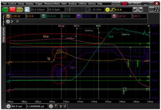
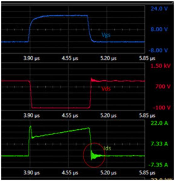
If you look at the switching characteristics taken by the Double-Pulse test system, you can see ringing in many places. Figures 1 and 2 below show two examples.
Various oscillation seen on off-characteristics of IGBT
Fast ringing on the drain current of SiC MOSFET when it becomes off
Noise due to Accuracy Limitation (Amplified data dispersion due to fast sampling)
An oscilloscope makes sampling very fast in less than nano-second intervals.
In case of the other instruments using Analog to Digital Converter (ADC), measurement time can be set manually before the measurement. Or, averaging is often used by specifying number of points to average. The specified measurement time is useful to reduce the noise. For example, SMU which provides very accurate current measurement capability uses multiple of power line frequency as measure time because this allows the significant reduction of the noise coming from power line.
Oscilloscope also provides various functions to reduce the noise. However, it is common practice to use the fastest sampling time to measure the characteristics and then data is processed to reduce noise (e.g. using digital filter). But there’s trade-off relation between measurement speed and accuracy. Therefore, the oscilloscope is in general not so accurate because the sampling speed is significantly faster than the other measurement instrument. In other words, if you take a close look at the measured data in tenths of nano-seconds, the data is spread over wide range or dispersed.
Differential Curve
Differential curve is often used to make data analysis. In case of Double-Pulse test, di/dt and dv/dt are mandatory items to use differential curve. However, if you make differential calculation using next two points in the characteristics, the results are almost divergent because the dispersion of the data and tiny time interval described above magnifies the error.
Hump seen at the Beginning of the Curve
When voltage or current characteristics start to change, unexpected hump or noise can be observed because of the sudden change causes voltage difference due to stray inductance or current difference due to stray capacitance. In case of fast signal, reflection of the signal due to impedance mismatch also causes unexpected hump. This may not be seen on the main current or voltage characteristics. But even though they are not seen in the main characteristics, once calculation such as di/dt is made, sometimes it becomes visible.
Applying low pass filter
If you look at Figure 9, there is significant ringing on the Vg.
Whether you see the ringing on Vg or not actually depends on not only on pure device characteristics with parasitic components of circuit but also on the circuit itself. For instance, if there’s protection circuitry on a gate driver board, it can act as a low pass filter which makes the oscillation not see-able.
Vgs curve is important because 10% or 90% of Vgs is used as a point of switching delay time for on or off. If you have ringing as seen in Figure 1, it is better to apply low pass filter. The frequency should be set using an external parameter. The following example uses 20 MHz digital LPF in the oscilloscope.
You can see that the Vgs curve is nicely smoothed out and the ringing characteristics don’t make the erroneous 10% of Vgs pick-up.
Applying Digital LPF (20 MHz) to Vge
When calculating gate charge, the same digital filter can be applied. But compared to Vgs, it is not critical to apply digital filter to Ig because the final data using Ig is integration and therefore the error caused by the ringing is somewhat diluted and doesn’t cause substantial error.
In case of Figure 2 above, the very fast ringing seen on the drain current is expected because no test system completely eliminates parasitic inductance and the MOSFET always has capacitance.
If the low current range needs to be used for parameter extraction, it is better to apply digital LPF to eliminate the effect of the ringing. It is possible to calculate the ringing frequency by doing the calculation using the measured data and apply half or ¼ of the ringing frequency for the digital filter.
However, in the case of a MOSFET, the current value is not used to extract timing related parameters. So, it doesn’t matter if you see very fast ringing seen in Figure 2.
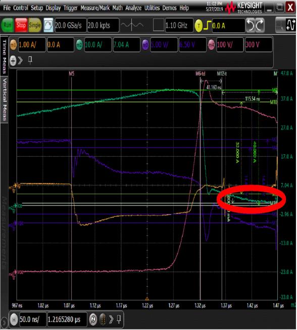
The following is another example applying 30 MHz LPF for reverse recovery.
Applying 30 MHz Digital LPF for reverse recovery
Applying Smoothing
For IGBTs, there’s requirement to take very low current values (2%) for timing parameter extraction.
Because the current is very low and almost flat, and the sampling speed is very fast, you see the small noise on the Ice over time. For this type of data, it is better to apply smoothing or averaging.
Let me explain the case for threshold voltage extraction using gm in static characterization. In this case, 100 points over characteristics changing range is more than enough. So, common technique is to use averaging (or long integration time) to smooth out the curve so that gm curve becomes clean.
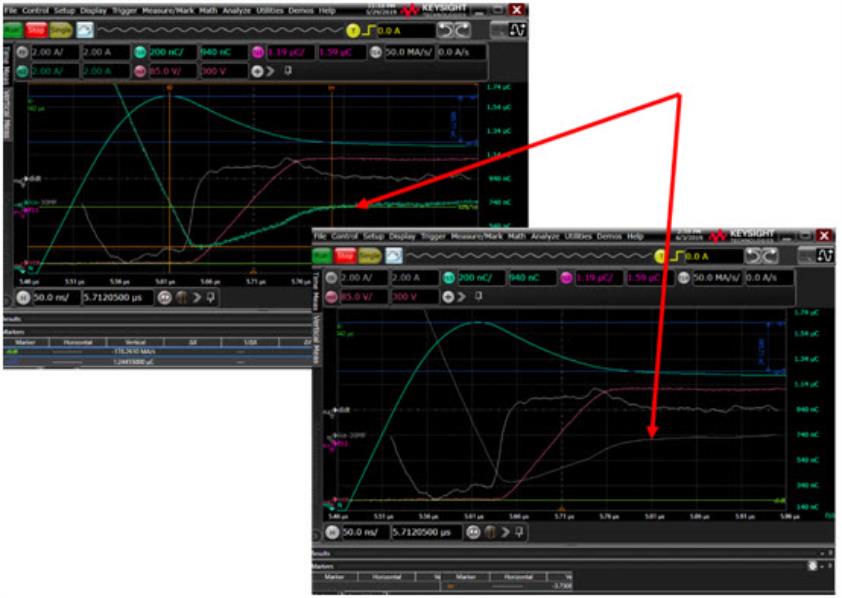
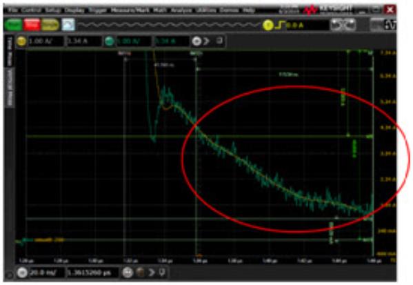
Applying smoothing (200) for Ice
If you look at the above graph, the Ice is slowly decreasing over 10ms. Here, the sampling speed is 20 GSa/s, which means 50 ps interval. Over the range of 10ms, there are 200k points. For drawing smooth curve, the curve needs to be decreased to 1000 or so. Which means, it is fine to apply averaging using 200 to 100 points. In order to eliminate or reduce the noise due to oscilloscope fluctuation, it’s better to apply smoothing rather than digital LPF.
Zoomed view (200 Smoothing)
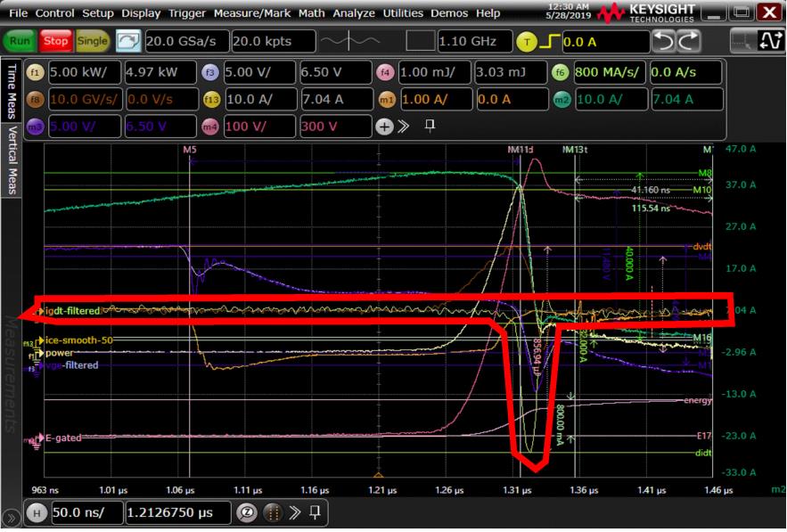
The other characteristics which require smoothing (or which can be LPF) are di/dt and dv/dt.
As described earlier, these characteristics simply have too much noise due to the nature of calculation. The subtle difference is magnified in this type of differential curve generation.
By applying smoothing, the curves look like following. It will help to accurately find the peak values or the reflection points.
Applying Smoothing to di/dt
The number of points for dv/dt and di/dt are too many just like the case for Ice described above.
So, averaging or smoothing, even though a big number is specified, won’t affect the end results.
Low Pass Filter Vs. Smoothing
For drain/collector current
Smoothing is in general better because it doesn’t give negative impact on the high bandwidth of shunt resistor
However, a good ringing seen in figure 2 due to fast device switching and parasitic inductance and the output capacitance of DUT, applying digital filter is good.
For drain/collector voltage
Neither smoothing or LPF is in general necessary.
For gate voltage
Digital LPF is better. 20 MHz can be a good number. But it is better for user to set the value.
For gate current
Noise is also seen on gate current. Using digital LPF is better. 20 MHz can be a good number. But it is better for user to set the value.
For differential curve like di/dt or dv/dt
After calculating di/dt curve or dv/dt curve, using digital LPF gives smoother curves. 100 MHz can be a good number. But it is better for user to set the value.
For reverse recovery current
Smoothing is better (even though LPF was used in the above example.)
Avoiding Hump
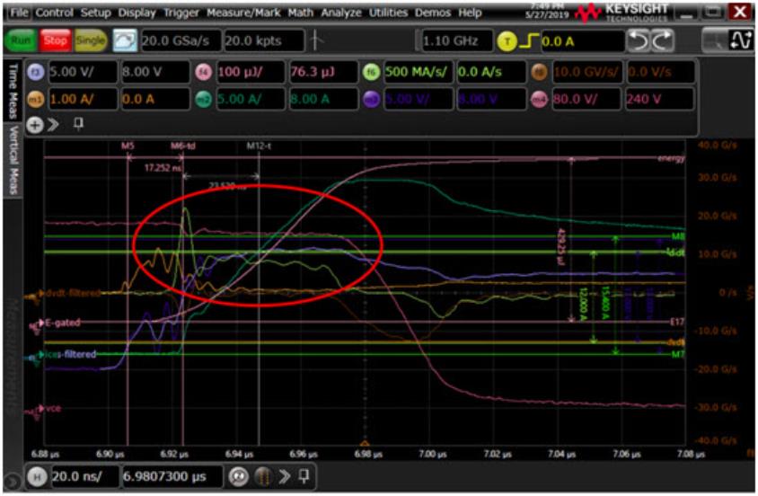
Avoiding the first hump (light green di/dt curve in red circle) for parameter extraction
Figure above shows on characteristics of an IGBT. Because of the Vge ringing, Ice is fluctuating at its onset.
Therefore, the di/dt curve (light green in red circle) shows a big hump at the beginning. The max di/dt needs to be taken from 10% to 90 % (12.0 A shown with light green markers) of Ice. However, in this case, this range gives an error because the di/dt is affected by the initial ringing. The hump must be avoided. The software should check the first minimum value in the di/dt curve before finding the maximum di/dt. (Note: This one also has to be checked when using the de-embedding. There’s possibility for de-embedding to reduce unnecessary sudden change of current because the influence of insertion inductance is reduced.)
