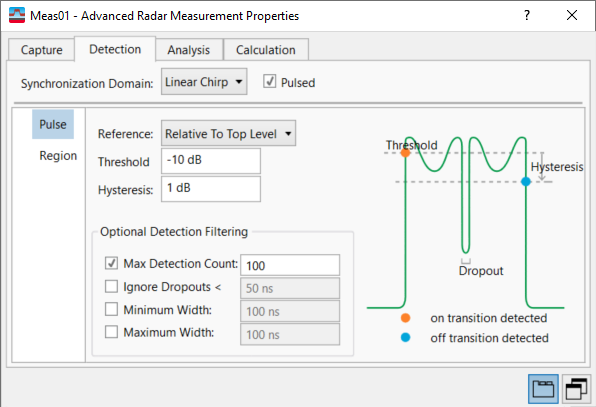
Pulse Panel (Advanced-Radar/Hopping)
Menu Path:
The Pulse panel is available when Synchronization Domain is either Amplitude (Pulsed) or Linear Chirp with the Pulsed checkbox selected.
The Pulse panel provides inputs to configure how unique pulses are detected in the Synchronization Domain.
If the noise floor of your signal is particularly high, this could interfere with the calculation of the Top/Base of the pulse, and thus interfere with the detection of the pulse. Consider using a Top/Base Calculation Method of Mean to compensate for this. This setting can be found on the Calculation tab under the Metric Calculation Thresholds grouping.

The following pulse detection parameters are available:
-
Reference -- Defines the level to be used as a reference for the pulse detection threshold. You can select a reference "Relative To Top Level", "Relative To Base Level", "Relative To Range", "Equal to Trigger", or you can select an "Absolute” reference level. “Top Level” and “Base Level” refer to the positions portions of the pulse (i.e. the pulse top and the base of the pulse).
-
Use First Chan for Reference -- Defines whether the Channel 1 Top/Base Levels are used as a reference for the Detection Threshold. When enabled (true), the Channel 1 Top/Base Levels will be used as a reference for calculating Threshold. If set to false, each channel will use its own Top/Base Level as a reference for the Threshold. This property does not affect calculation if Reference is set to Absolute.
-
-
Threshold -- Determines whether a pulse is detected or not. The top of a pulse must exceed the threshold in order to be detected. The threshold is defined in dB in relation to the defined reference, or as an absolute threshold in dBm deciBels referenced to a milliWatt: dB relative to 1 milliwatt dissipated in the nominal input impedance of the analyzer. By default, the threshold is in (dB). The threshold is in (dBM) when the Reference is set to "Relative to Range" or "Absolute".
-
Hysteresis --Defines a hysteresis for pulse detection in dB in relation to the defined threshold. As long as the signal does not exceed the hysteresis, the next threshold crossing is ignored. If the amplitude in the signal drops below the threshold + hysteresis, then the end of the pulse is considered to have been reached.
Optional Detection Filtering
-
Max Detection Count -- Specifies maximum number of pulses to be detected and reported from acquisition when Max Pulse Count is checked.
-
Ignore Dropouts -- When checked, rejects short drops in amplitude during pulse "on" time . These are typically side effects of intra-pulse modulation (Barker phase shift, FSK Frequency Shift Keying: A form of modulation using multiple carrier frequencies to carry the digital information. The most common is the two frequency FSK system using the two frequencies to carry the binary ones and zeros. or frequency-stepping, etc.), where the magnitude of the pulse briefly falls. The value you set, in seconds, is the maximum Pulse Power Dropout duration (sec) to be ignored during pulse detection.
-
Minimum Width -- Specifies minimum Pulse Width (sec) for a pulse to be included in detected pulse results when Min Pulse Width is checked.
-
Maximum Width -- Specifies maximum Pulse Width (sec) for a pulse to be included in detected pulse results when Max Pulse Width is checked.
See Also
Advanced-Radar/Hopping Measurement Properties Dialog Box
