Note: The Integrated Pulse App (Opt 008) replaces this application.
The Narrowband Pulsed Application is a Visual Basic program that provides a user interface for making pulsed measurements.
In this topic:
The following enhancements were made In PNA Rev. 7.2:
Learn about the Wideband Pulsed Application.
For more conceptual information see our Pulsed Measurement App Notes.
See PNA-X Block Diagram of IF Path / Pulse Generators / Source Modulation
Required Options and Equipment
The PNA H08 option provides the Narrowband Pulsed Application. The following options are also required. If your PNA does not have the required options, a message is displayed on the screen. For more information, see Pulsed-RF Measurements Configuration Guide
PNA-X models: Opts 021. 022. and 025 greatly enhance speed, performance, and convenience.
PNA-X Opt 224 (2-port Dual Source) select the 2-port Dual Source Configuration in the Path Configuration dialog to provide Pulse modulation on both port 1 and port 2.
Use the Pulse I/O connector to access the internal pulse generators
See the PNA-X IF Path Configuration block diagram which includes the Pulse Modulators and Generators.
PNA-L models: HO8 NOT available
Keysight 81104A or 81110A Pulse Generator with ONLY the 81105A or 81111A output modules. The 81112A module does NOT have selectable 50 ohm/1K ohm output impedance/load compensation to drive the 1K ohm PNA IF gates. For more information, see the 81100 Family of Pulse Pattern Generators Technical Specifications at: http://literature.cdn.Keysight.com/litweb/pdf/5980-1215E.pdf
Each 81110A Pulse Generator has two output modules. Each output can drive a PNA IF Receiver or Source Modulation (Z5623A H81). Connect the Pulse Generators as follows:
81110A front panel connectors

Connect GPIB cables to the 81110A and PNA.
Connect the PNA 10 MHz Ref Out to the 81110A 10 MHz IN.
If using two 81110As for a total of 4 outputs, then connect the TRIGGER OUT of one to the EXT INPUT of the other 81110A.
Connect the 81110A OUTPUTs to the PNA rear panel IF inputs to be gated. The outputs are mapped in the Pulsed Generator Configuration dialog box.
|
PNA |
H81 |
|
Src Out |
Source IN |
|
CPLR THRU |
CPLR THRU |
|
RCVR R1 IN |
RCVR R1 Out |
Using the Narrowband Pulsed Application
How to start the Narrowband Pulsed Application |
|
|
Using front-panel |
Using Menus |
|
|
The PNA front-panel Numeric Entry and Navigation keys can be used for dialog box input. Also, a keyboard can be used to enter values, including alpha characters for prefixes (for example, u for usec.) . After typing values, first press Enter, then press Tab to go to the next field.
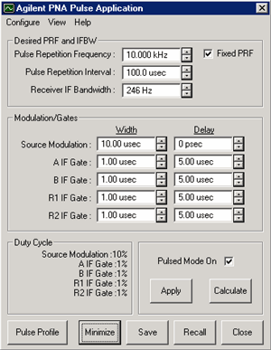
The following is an image of the main dialog box:

See Block Diagram of IF Path / Pulse Generators / Source Modulation ConfigureYou can configure more than one channel to make pulsed measurements, but the channels must use the same pulse generator settings. Only the Keysight 81110A Pulse Generator is supported with the Narrowband Pulsed Application. Refer to the 81110A documentation for pulse repetition frequency and duty cycle capabilities. See AlsoEdit / Undo Pulse Application settings revert to those when Apply was last pressed. Desired PRF and IFBW Enter the DESIRED values. When Calculate is pressed, one or both of these values may change. Pulse Repetition Frequency (PRF): Frequency of the pulses from the Pulse Generator. Pulse Repetition Interval: 1/ PRF Changes to either PRF or this setting changes both. Receiver IF Bandwidth: IF Bandwidth of the PNA. Choose a setting from 1 Hz to 10 KHz. Fixed PRF When checked, (default setting) the Calculate algorithm will NOT adjust the PRF, but only change the IF Bandwidth. When cleared, both the PRF and IF Bandwidth values are adjusted as necessary. Note: On PNA's with DSP version 4, the Calculate algorithm will NOT find nulling at several PRF frequencies. If this error is returned, add a small offset to the PRF (for example, 2.1 MHz instead of 2 MHz) or clear the Fixed PRF checkbox. Modulation/Gates The Source Modulation and four PNA receiver gates can each have their own, or share, Pulse Generator outputs. Shared outputs have identical Width and Delay values. To configure and enable outputs, click Configure, then Pulse Generators to launch the Pulsed Generator Configuration dialog box. Note: Option 036 and 037 limits the Source Modulation width to 117 ns. Width Pulse Width. Delay The delay that occurs before the pulse.
Duty Cycle Calculated Duty Cycle of the source and each of the selected receivers. Updated when Calculate is pressed. Pulse Mode On When this box is checked, the PNA is enabled for Pulsed measurements. The PNA Status Bar annotation indicates the following:
Apply All selections are sent to the pulse generator and the active channel of the PNA. Calculate All selections are calculated and valid PRF and IFBW values are entered in their fields. If these settings are not acceptable, try changing the values you previously entered and click Calculate again. When acceptable values are attained, click Apply to send these values to the pulse generator and PNA. Pulse Profile Launches the Pulse Profile dialog box. Same as clicking View / Pulse Profile. If not available, check Pulse Mode ON, click Calculate, then Apply. Minimize Click to minimize the dialog box to make changes in the PNA application. To see the dialog again, select Macro, Pulse, or turn the Status Bar ON. Save All settings from the Narrowband Pulsed Application are saved in a *.ppf file. These settings are NOT saved with PNA instrument state. Recall Restore settings from the specified *.ppf file that were previously saved. Close Closes the dialog box without saving changes. |
How to configure Pulse Generators / Modulators and Receivers |
|
From the Pulse App main dialog box
Learn about...
|

|
Notes:
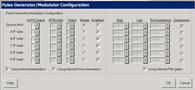
Configures either the internal pulse generators (PNA-X models with relevant options), or Keysight 81110A Pulse Generator outputs. You can configure each 81110A Pulse Generator with either one or two 81111A output modules. The Source Mod and four PNA receiver gates can each have their own, or shared, pulsed generators allowing identical Width and Delay values which are selected on the Main dialog. To share an external generator output between one or more PNA inputs, use the same GPIB address and output module for each PNA input. Internal Pulse Gen Output (available ONLY on the PNA-X opt 025) Specify the Pulse Gen (1 through 4) to use to modulate each of the PNA receiver IF gates or Sources. External Pulse Generator settings GPIB Addr: The GPIB address of the 81110A. Output: The output module of the 81110A. Master: The 81110A that uses the 10 MHz reference signal from the PNA. Enabled: Turns the pulse output ON. External Gate/Modulator settings High: Specify a 'TTL-High' voltage level Low: Specify a 'TTL-Low' voltage level Ext Impedance: Impedance of the modulator used to create the pulse. Complement: When this box is cleared, TTL HIGH is the pulse. When checked, TTL LOW is the pulse. Using Internal Modulators When this box is checked, the voltage, impedance, and complement values are forced to settings that prevent damage to the internal modulator. Using Internal Pulse Generators Makes the appropriate settings on this dialog available. Using Internal PNA gates When this box is checked, the voltage, impedance, and complement values are forced to settings that prevent damage to the internal gates. |

|
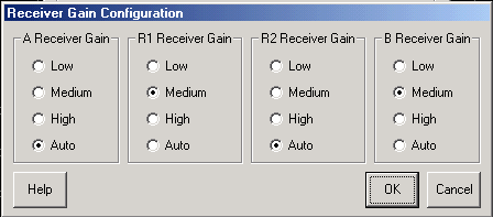
See Block Diagram of PNA-X IF Path / Pulse Generators / Source Modulation This dialog may look different depending on the PNA model and number of receivers available. Sets the gain of each PNA receiver manually or automatically. Auto - The PNA selects the best gain level to make pulsed measurements. Use the following to manually set the gain for each receiver. Low - about 0 dB of gain Medium - about 17 dB of gain High - about 24 dB of gain The PNA-X has the following attenuation settings: Low - 30 dB of attenuation Medium - 15 dB of attenuation Hi - 0 dB of attenuation |
To perform a calibration in pulse mode (option H08), first configure and apply the pulse parameters (PRF, Pulse Width, Delays, IF gating, and so forth) before calibrating the system. This will ensure the PNA is configured properly during the calibration and measurement.
When performing Unknown Thru or TRL calibrations, ALL receivers must be gated. Otherwise, the error terms will not be correct after the calibration has completed. This can be accomplished by either having a separate pulse generator output for each of the IF gates, or by connecting pairs of the IF gates together with BNC-T's. For example, if the pulse generator does not have enough outputs, then connect the R1 and R2 IF gates to the same pulse generator output. Also, connect the A and B IF gates to either separate outputs (recommended) or one output (reduces flexibility). The error terms will then be valid after the calibration is complete.
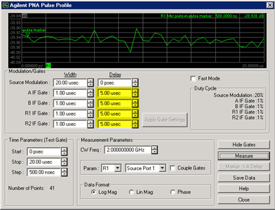
Pulse profiling provides a time domain view of the pulse envelope. Profiling is performed using a measurement technique that "walks" a narrow receiver "snapshot" across the width of the pulse. This is analogous to using a camera to take many small snapshots of a wide image, then piecing them together to form a single, panoramic view.
Pulse Profiling can be performed using ratioed or unratioed measurements.
Pulse Profiling is performed at a single CW frequency.
|
How to perform Pulse Profiling |
|
From the Pulse App main dialog box, Click the Pulse Profile button. or:
If this setting is unavailable, check Pulse Mode ON, click Calculate, then Apply. |

|
Learn about Pulse Profiling (scroll up) See Block Diagram of PNA-X IF Path / Pulse Generators / Source Modulation Modulation / GatesThese setting duplicate those found on the main Pulse App dialog box. In Pulse Profile, the Gate Delay settings (highlighted in yellow) are significant only with certain Measurement Parameter and Couple Gates settings. Time ParametersStart, Stop These two combine to make the window of the assembled pulse profile. To view the entire pulse, the start and stop values must be at least as wide as the Source Modulation Width plus Delay value. Step Each consecutive snapshot is incremented by this value until the stop value is reached. Therefore, the number of points for the pulse profile measurement can be calculated as: (Stop - Start) / Step. The higher the number of points, the longer it takes to make the measurement. Measurement ParameterCW Freq. Frequency of the PNA source. Source Port The PNA port supplying the source power. Only required for single receiver (unratioed) measurements. Param(eter) Only those receiver gates (and relevant measurements) that are configured in Pulsed Generator Configuration are available. Note: When a single receiver (unratioed) is selected, Gate Delay Settings (highlighted in yellow on above dialog image) are ignored. If the reference receiver gate is NOT configured, the average of the Source Modulation pulse is used as the reference. For example: With S21 Selected, but ONLY B receiver gate is configured, then...
Coupled Gates Used when the appropriate receiver gates are configured for your S-parameter measurement ONLY. This setting is ignored when a single receiver (Param) is selected.
Data Format Log Magnitude, Linear Magnitude, or Phase (only available if S-parameter selected). ButtonsShow Gates Allows you do change the receiver gating width and delay while looking at the results. Apply Gate Settings Click after making changes to gate settings. Continuous Sweep Check, then click Measure, to continuously measure pulse profiling. Measure Click to start the pulse profile measurement. Becomes Stop when continuously sweeping. Marker to Delay After making a measurement, you can drag the display maker to any point along the trace. Click this button and the marker time is entered into the Receiver Delay field on the main dialog box. Save Data Saves time domain data to the PNA hard drive in any of the following formats:
|
||||||||||||||
Signal Reduction versus Gate Width
Signal Reduction versus Gate WidthPRF = 1 MHz |
|
The following two figures show the performance of the internal IF gates as the width is narrowed.
The following is a zoomed image of the shaded area (above).
See the specifications for the option H11 and option H08.
|
Pulsed Frequency Converter Measurements
The Narrowband Pulsed Application works with both FCA (option 083) and standard Frequency Offset (opt 080) measurements. On the Configure menu, check Converter Measurements. When checked, this setting prevents the Narrowband Pulsed Application from overwriting frequency offset values. This may limit the number of PRF and IFBW solutions that are returned when Calculate is pressed on the main Pulsed Application dialog box.
Note: Pulse Profiling can NOT be performed with frequency converter measurements.

Writing your own Narrowband Pulsed Application
You can use the Narrowband Pulsed Application or use an example program as a template for making your own Narrowband Pulsed Application.
The Narrowband Pulsed Application uses a custom .dll to perform the calculations that are necessary to make pulsed measurements. Use the COM Method below to send and return values to agilentpnapulsed.dll. Then use SCPI or COM commands to control the PNA.
|
COM Example Program |
|
|
SCPI Example Programs |
|
|
COM Methods |
|
|
SCPI commands |
|
|
COM commands |
To create your own Narrowband Pulsed Application, or run the Narrowband Pulsed Application from a remote PC, you must do the following:
Copy the following files from the PNA C:/program files/Keysight/network analyzer/ to a directory on your PC.
agilentpnapulsed.dll
OffsetList.txt
prfbw.txt
prfbwmixer.txt
To register the ActiveX DLL in Microsoft Windows Operating System:
From a command prompt on your PC, navigate to the directory where you copied the DLL.
Type: regsvr32 agilentpnapulsed.dll and press Enter
For Operating Systems other than Windows, see their associated help files to learn how to register DLL files.