Probe Calibration
Use the :CALibrate:PROBe:CHANnel:STARt command to run a probe calibration. During a probe calibration, the FlexDCA determines the gain and offset of a probe and then applies those factors to the calibration of the channel. Use the :CALibrate:OUTPut command to change the dc voltage at the DCA-X's front-panel Cal Out connector, which is used during the calibration. The default level is 5.0 mV. To query the status of a probe calibration, use the :CALibrate:PROBe:CHANnel:STATus? command.
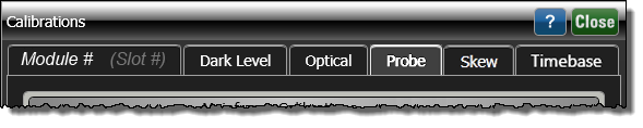
Calibration commands correspond to the features in the Calibration dialog. You can click on the tabs in this picture to learn about the different calibrations.
A probe calibration requires:
- A supported active probe as identified with the
:CHANnel:PROBe:IDcommand. - A supported module that includes a Probe Power connector: 54752A, 54754A, 83484A, 83486A, 86108A, 86108B, and 86112A.
- The probe must be connected to an electrical input channel with probe power supplied by the DCA-X module's front panel Probe Power connector. After the active probe is detected, FlexDCA automatically adds a Probe Setup block to the Channel External Hardware Setup dialog. The DCA-X cannot detect any information about the attached probe.
The calibration is performed using a DC level from the DCA-X's front-panel DC Cal output (:CALibrate:OUTPut command). The DCA-X calibrates the voltage at the tip of the probe or the cable input. The probe calibration is performed on electrical channels only and is only performed on one channel at a time. A probe calibration does not have to be performed but is recommended.
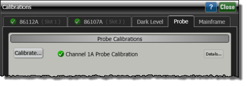
The Probe tab is only shown if a DCA-X has automatically detected a supported active probe on a 54752A, 54754A, 83484A, 83486A, 86108A, 86108B, or 86112A module.
Do not remove a module from the DCA-X during a calibration.
If your probe does not use the probe power connection or it is a passive probe, use the :CHANnel:PROBe:ATTenuation, :CHANnel:PROBe:ID, and :CHANnel:PROBe:MODE commands to enter the probe's model number, attenuation, and mode (single or differential).
You should calibrate a probe before making any critical measurements.
Typically, probes have standard attenuation factors, such as divide by 10, divide by 20, or divide by 100. If the probe being calibrated has an unusual attenuation, like 3.75, the instrument will adjust the vertical scale factors to an unusual number, such as 3.75 V/div.
The input circuits can be damaged by electrostatic discharge (ESD). Therefore, avoid applying static discharges to the front-panel input connectors. Prior to connecting any coaxial cable to the connectors, momentarily short the center and outer conductors of the cable together. Avoid touching the front-panel input connectors without first touching the frame of the instrument. Be sure that the instrument is properly earth-grounded to prevent buildup of static charge. An anti-static mat and wristband are strongly recommended.
To calibrate a probe
- If you are calibrating an N2800A-series probe, skip this procedure and perform the procedure that is provided in the User's Guide help.
- Connect the probe to the electrical channel you want to use.
- Use the
:CHANnel:PROBe:ATTenuation,:CHANnel:PROBe:ID, and:CHANnel:PROBe:MODEcommands to enter the probe's model number, attenuation, and mode (single or differential). - Connect the probe tip to the front-panel DC Cal output.
- Click Tools > Calibrations and click the Probe tab.
- Send the
:CALibrate:PROBe:CHANnel:STARtcommand to start the calibration.
Do not remove the module or probe tip during the probe calibration.
For accurate calibration results, ensure there is a ground between the probe ground tip and the instrument mainframe.