:CHANnel:ATTenuator:STATe
Command Syntax
:CHANnel{1:8}{A|B|C|D}:ATTenuator:STATe {OFF | ON}
Where the required specifier {1:8}{A|B|C|D} identifies a channel by its module slot number and channel letter. For example, channel 3C (CHANnel3C).
The channel specifier will fail if it does not include a slot number. If instead the suffix's channel letter is missing, the command defaults to letter A. As a result, the best practice is to always explicitly specify the channel by including both the module slot number and channel letter.
Query Syntax
:CHANnel{1:8}{A|B|C|D}:ATTenuator:STATe?
Description
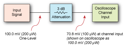
Turns on and off compensation for external attenuator in the test setup. This allows FlexDCA to report measurement values as if the measurements were made before the attenuator rather than at the oscilloscope's channel input. You can select to enter the amount of attenuation in decibels or as a voltage ratio (:CHANnel:ATTenuator:DECibels or :CHANnel:ATTenuator:RATio).
When entering attenuation in decibels, enter the attenuation as a positive value. Gain is implied when you enter negative decibel values.
For example, if your test setup included an electrical signal with 3 dB of attenuation, a signal with a 100.0 mV one level (before the attenuation) would be measured as 70.8 mV at the oscilloscope's channel input. However, after entering 3 dB (or 1.413:1 ratio) of attenuation compensation, the corrected oscilloscope measurement would read 100 mV.
Optical Signals
Attenuation is expressed differently depending on the type of signal applied. For an optical signal the following equation applies. With a 6 dB attenuation setting, the signal is interpreted as being four times the channel input level.
Electrical Signals
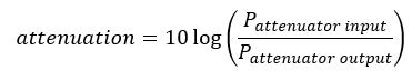
The following equation shows attenuation for an electrical signal. For a 6 dB attenuation setting, the signal is interpreted as being double the channel input level.

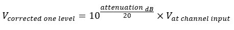
With an attenuation factor expressed in decibels, the conversion of the channel input value would be:
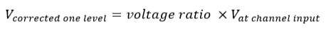
With an attenuation factor expressed as a voltage ratio, the conversion of the electrical channel input value would be:
Effects on Channel Settings
When compensating for an external attenuator, the channel settings change in the following ways:
- The unit values and amplitude of the markers and vertical measurements reflect the signal at the input of a transducer, probe, attenuator, or amplifier.
- The maximum and minimum vertical scale settings change by a specified factor.
- Offset minimum and maximum values change by a specified factor.
Gain is implied when you enter negative decibel values or ratios of less than 1:1 in the Attenuation field.
The default attenuation value is 1:1 when no active probes are connected to the instrument. When an active probe such as the N2800A is connected, the default value is the nominal value of the probe and the Reset Attenuation to 1:1 button is unavailable.
For electrical channels, the value displayed in the Attenuation field is the same value displayed in the N1000A's Probe tab of the All Calibrations dialog; changing one value will change the value of the other.
For both power and electrical signals, the available attenuation ratio range is 0.0001:1 to 1,000,000:1. This is equivalent to –40 dB to 60 dB for power, and –80 dB to 120 dB for electrical signals.
Use the :CHANnel:ATTenuator:RESet command to reset the attenuation to the default value of 0 dB (1:1). See also external transducer compensation.
Requires FlexDCA revision A.01.80 and above.
Example Command
:CHANnel2A:ATTenuator:STATe ON