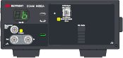
N1092A/B/C/D/E Specifications
N1092A/B/C/D/E DCA-M multiple-channel optical/electrical sampling oscilloscope specifications and characteristics apply when the temperature is within the range noted below. Use the DCA-M's rear panel USB Type B connector to connect the DCA-M to a DCA-X mainframe or to N1010A FlexDCA on a PC. The DCA-M is connected as a USB device.
Minimum Firmware Version. The N1092A/B/C/D/E must be controlled from a PC or DCA-X that is running a FlexDCA with minimum FlexDCA firmware versions shown in this list. However, if the N1092-series DCA-M, regardless of option, has a serial number ≥ MY62100101 FlexDCA firmware version A.06.90 or later is required.
- A.05.40 (N1092C/E)
- A.05.40 (N1092A/B/D)
- A.06.00 (N1092X Option 30A)
- A.06.40 (N1092X Option 40A)
- A.06.61 (N1092X Option 40A, CDR)
All specifications describe warranted performance over the temperature range +10C to + 40C (unless otherwise noted). The specifications are applicable after the temperature is stabilized, which occurs after 1 hour of continuous operation and within ±5C of the module's calibration temperature.
The N1092/4x time base has humidity-sensitive components. The amount of moisture accumulated in the instrument depends on the length of time it has been powered off as well as ambient humidity. Under certain measurement conditions and environments, the jitter may be temporarily higher than the specified limit after a unit has been recently turned on. If the jitter exceeds the specification it is recommended to allow the instrument to stay powered on for greater than 24 hours to allow the humidity within the system to stabilize. Many performance parameters are enhanced through frequent, simple user calibrations.
Specifications describe warranted performance. Characteristics provide useful, nonwarranted information about the functions and performance of the instrument. Characteristics are printed in green italics. Characteristics are applicable after the temperature is stabilized, which occurs after 1 hour of continuous operation and within ±1C of the module's calibration temperature.
Nominal Value indicates the expected, but not warranted, value of the parameter.
Factory Calibration Cycle. For optimum performance, the N1092A/B/C/D/E should have a complete verification of specifications once every 12 months.
The Mains wiring and connectors shall be compatible with the connector used in the premise electrical system. Failure to ensure adequate earth grounding by not using the correct components may cause product damage, and serious injury.
This product is designed for use in INSTALLATION CATEGORY II and POLLUTION DEGREE 2 environment.
N1092A (Option N28) optical channel specifications
| Item | Description | ||
|---|---|---|---|
| Optical Channel Count | 1 | ||
| Optical Channel Bandwidth, −3 dBo | 28 GHz (characteristic) 1 | ||
| Nominal Wavelength Range | 830 nm to 1600 nm | ||
| Factory calibrated wavelengths 2 | 850 nm (±20 nm) 1310 nm (±20 nm) 1550 nm (±20 nm) |
||
| User calibration wavelength range | 830 nm to 1600 nm | ||
| Filter Frequency Response (all values relative to 2 MHz) | Description | ||
| Attenuation @ 50 Hz | < 4 dB (Characteristic) | ||
| Attenuation @ 4 kHz | > 27 dB (Characteristic) | ||
| Attenuation @ 280 kHz | < 4 dB (Characteristic) | ||
| RMS Noise (Characteristic) | 850 nm | 1310 nm | 1550 nm |
| 100GBASE-SR4 TDEC (12.6 GHz filter) | 5 μW | 3 μW | 3.5 μW |
| 20.625 Gb/s | 7 μW | 5 μW | 5 μW |
| 25 Gb/s Ethernet (25.78125 Gb/s) | 8 μW | 5.5 μW | 5.5 μW |
| 400GBASE-SR16 (26.5625 Gb/s) | 8 μW | 5.5 μW | 5.5 μW |
| Ethernet OTU4 FEC/ITU-T G.959.1 (27.952493 Gb/s) | 9.5 μW | 6 μW | 6 μW |
| 32G Fibre Channel (28.05 Gb/s) | 9.5 μW | 6 μW | 6 μW |
| RMS Noise (Maximum) | 850 nm | 1310 nm | 1550 nm |
| 100GBASE-SR4 TDEC (12.6 GHz filter) | 7 μW | 5 μW | 5.5 μW |
| 20.625 Gb/s | 9 μW | 7 μW | 7.5 μW |
| 25 Gb/s Ethernet (25.78125 Gb/s) | 10 μW | 7 μW | 7.5 μW |
| 400GBASE-SR16 (26.5625 Gb/s) | 10 μW | 7 μW | 7.5 μW |
| Ethernet OTU4 FEC/ITU-T G.959.1 (27.952493 Gb/s) | 11 μW | 8 μW | 8.5 μW |
| 32G Fibre Channel (28.05 Gb/s) | 11 μW | 8 μW | 8.5 μW |
| Optical Sensitivity (Characteristic) 3 | 850 nm | 1310 nm | 1550 nm |
| 20.625 Gb/s | –11.5 dBm | –13.0 dBm | –13.0 dBm |
| 25 Gb/s Ethernet (25.78125 Gb/s) | –11 dBm | –12.5 dBm | –12.5 dBm |
| 400GBASE-SR16 (26.5625 Gb/s) | –11 dBm | –12.5 dBm | –12.5 dBm |
| Ethernet OTU4 FEC/ITU-T G.959.1 (27.952493 Gb/s) | –10 dBm | –12 dBm | –12 dBm |
| 32G Fibre Channel (28.05 Gb/s) | –10 dBm | –12 dBm | –12 dBm |
| Scale Factor Specifications (per division, 8 divisions) | Description | ||
| Minimum | 5 μW | ||
| Maximum | 500 μW | ||
| CW Offset Range 4 | +1.0 mW to −3 mW | ||
| CW Accuracy 5 | Description | ||
| Single-Mode | ± 15 μW ± 1.5% of reading ± connector uncertainty (Characteristic) ± 30 μW ± 3% of reading ± connector uncertainty |
||
| Multimode | ± 25 μW ± 10% of reading ± connector uncertainty (Characteristic) |
||
| Maximum Measureable Input Power | Description | ||
| 100GBASE-SR4 TDEC (12.6 GHz filter) 6 | 4 mW at 500 μW/division scale factor (Characteristic)
3 mW at 500 μW/division scale factor |
||
| 20.625 Gb/s | 4 mW at 500 μW/division scale factor | ||
| 25 Gb/s Ethernet (25.78125 Gb/s) | 4 mW at 500 μW/division scale factor | ||
| 400GBASE-SR16 (26.5625 Gb/s) | 4 mW at 500 μW/division scale factor | ||
| Ethernet OTU4 FEC/ITU-T G.959.1 (27.952493 Gb/s) | 4 mW at 500 μW/division scale factor | ||
| 32G Fibre Channel (28.05 Gb/s) | 4 mW at 500 μW/division scale factor | ||
| Average Power Monitor Range | −30 dBm to 0 dBm (850 nm) −30 dBm to +6 dBm (1310 nm) −30 dBm to +6 dBm (1550 nm) |
||
| Average Power Monitor Accuracy 7, 8 | Description | ||
| Single-Mode | 200 nW ± 5% of reading ± connector uncertainty | ||
| Multimode | 200 nW ± 10% of reading ± connector uncertainty (Characteristic) |
||
| Maximum Non-destruct Peak Power | 8 mW (+9 dBm) | ||
| Fiber Input 9 | 50/125 μm | ||
| Fiber Input Connector | FC/PC | ||
| Channel ADC | 16 bits | ||
With the 32G Fibre Channel reference receiver filter selected, −3 dBo is calculated from the −6 dBe point.
For the average power monitor and the channel vertical path.
Generally represents the power level where an ideal eye diagram will approach 0% mask margin due to the noise of the oscilloscope. Provides a non-specified figure of merit to compare sensitivities of various optical channels. These values are calculated from the characteristic noise values.
Referenced two divisions from screen bottom.
Single marker, referenced to power sensor.
When a TDEC filter is used any portion of the signal that is displayed above 3 mW is not warranted.
Due to variations in mode-filling conditions, the measured power in multimode fiber will vary more than the measured power in single-mode fiber. For users needing the most accurate power measurements, use an optical power meter for multimode power measurements.
Average power monitor accuracy is tied to the calibration accuracy of the power sensor.
Compatible with external fibers with < 50 μm cores.
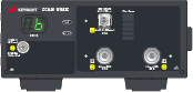
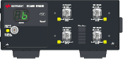
N1092A/B/C/D/E (Option 30A) optical channel specifications
| Item | Description | ||
|---|---|---|---|
| Optical Channel Count | 1 (N1092A/C) 2 (N1092B/E) 4 (N1092D) |
||
| Optical Channel Bandwidth, −3 dBo | 28 GHz (characteristic) 1 | ||
| Nominal Wavelength Range | 830 nm to 1600 nm | ||
| Factory calibrated wavelengths 2 | 850 nm (±20 nm) 1310 nm (±20 nm) 1550 nm (±20 nm) |
||
| User calibration wavelength range | 830 nm to 1600 nm | ||
| RMS Noise (Characteristic) | 850 nm | 1310 nm | 1550 nm |
| 100GBASE-SR4 TDEC (12.6 GHz filter) | 5 μW | 3 μW | 3.5 μW |
| 20.625 Gb/s | 7 μW | 5 μW | 5 μW |
| 25 Gb/s Ethernet (25.78125 Gb/s) | 8 μW | 5.5 μW | 5.5 μW |
| 400GBASE-SR16 (26.5625 Gb/s) | 8 μW | 5.5 μW | 5.5 μW |
| Ethernet OTU4 FEC/ITU-T G.959.1 (27.952493 Gb/s) | 9.5 μW | 6 μW | 6 μW |
| 32G Fibre Channel (28.05 Gb/s) | 9.5 μW | 6 μW | 6 μW |
| RMS Noise (Maximum) | 850 nm | 1310 nm | 1550 nm |
| 100GBASE-SR4 TDEC (12.6 GHz filter) | 7 μW | 5 μW | 5.5 μW |
| 20.625 Gb/s | 9 μW | 7 μW | 7.5 μW |
| 25 Gb/s Ethernet (25.78125 Gb/s) | 10 μW | 7 μW | 7.5 μW |
| 400GBASE-SR16 (26.5625 Gb/s) | 10 μW | 7 μW | 7.5 μW |
| Ethernet OTU4 FEC/ITU-T G.959.1 (27.952493 Gb/s) | 11 μW | 8 μW | 8.5 μW |
| 32G Fibre Channel (28.05 Gb/s) | 11 μW | 8 μW | 8.5 μW |
| Optical Sensitivity (Characteristic) 3 | 850 nm | 1310 nm | 1550 nm |
| 20.625 Gb/s | –11.5 dBm | –13.0 dBm | –13.0 dBm |
| 25 Gb/s Ethernet (25.78125 Gb/s) | –11 dBm | –12.5 dBm | –12.5 dBm |
| 400GBASE-SR16 (26.5625 Gb/s) | –11 dBm | –12.5 dBm | –12.5 dBm |
| Ethernet OTU4 FEC/ITU-T G.959.1 (27.952493 Gb/s) | –10 dBm | –12 dBm | –12 dBm |
| 32G Fibre Channel (28.05 Gb/s) | –10 dBm | –12 dBm | –12 dBm |
| Scale Factor Specifications (per division, 8 divisions) | Description | ||
| Minimum | 5 μW | ||
| Maximum | 500 μW | ||
| CW Offset Range 4 | +1.0 mW to −3 mW | ||
| CW Accuracy 5 | Description | ||
| Single-Mode | ± 15 μW ±1.5% of reading ± connector uncertainty (Characteristic) ± 30 μW ±3% of reading ± connector uncertainty |
||
| Multimode | ± 25 μW ±10% of reading ± connector uncertainty (Characteristic) |
||
| Maximum Measureable Input Power | Description | ||
| 100GBASE-SR4 TDEC (12.6 GHz filter) 6 | 4 mW at 500 μW/division scale factor (Characteristic)
3 mW at 500 μW/division scale factor |
||
| 20.625 Gb/s | 4 mW at 500 μW/division scale factor | ||
| 25 Gb/s Ethernet (25.78125 Gb/s) | 4 mW at 500 μW/division scale factor | ||
| 400GBASE-SR16 (26.5625 Gb/s) | 4 mW at 500 μW/division scale factor | ||
| Ethernet OTU4 FEC/ITU-T G.959.1 (27.952493 Gb/s) | 4 mW at 500 μW/division scale factor | ||
| 32G Fibre Channel (28.05 Gb/s) | 4 mW at 500 μW/division scale factor | ||
| Average Power Monitor Range | −30 dBm to 0 dBm (850 nm) −30 dBm to +6 dBm (1310 nm) −30 dBm to +6 dBm (1550 nm) |
||
| Average Power Monitor Accuracy 7, 8 | Description | ||
| Single-Mode | 200 nW ± 5% of reading ± connector uncertainty | ||
| Multimode | 200 nW ± 10% of reading ± connector uncertainty (Characteristic) |
||
| Maximum Non-destruct Peak Power | 8 mW (+9 dBm) | ||
| Fiber Input 9 | 50/125 μm | ||
| Fiber Input Connector | FC/PC | ||
| Channel ADC | 16 bits | ||
With the 32G Fibre Channel reference receiver filter selected, −3 dBo is calculated from the −6 dBe point.
For the average power monitor and the channel vertical path.
Generally represents the power level where an ideal eye diagram will approach 0% mask margin due to the noise of the oscilloscope. Provides a non-specified figure of merit to compare sensitivities of various optical channels. These values are calculated from the characteristic noise values.
Referenced two divisions from screen bottom.
Single marker, referenced to power sensor.
When a TDEC filter is used any portion of the signal that is displayed above 3 mW is not warranted.
Due to variations in mode-filling conditions, the measured power in multimode fiber will vary more than the measured power in single-mode fiber. For users needing the most accurate power measurements, use an optical power meter for multimode power measurements.
Average power monitor accuracy is tied to the calibration accuracy of the power sensor.
Compatible with external fibers with < 50 μm cores.
N1092A/B/C/D/E (Option 40A) optical channel specifications without Option CDR
| Item | Description | |
|---|---|---|
| Optical Channel Count | 1 (N1092A/C) 2 (N1092B/E) 4 (N1092D) |
|
| Optical Channel Bandwidth, −3 dBo | 45 GHz (characteristic) 1 | |
| Nominal Wavelength Range | 1250 nm to 1600 nm | |
| Factory calibrated wavelengths 2 | 1310 nm (±20 nm) 1550 nm (±20 nm) |
|
| User calibration wavelength range | 1250 nm to 1600 nm | |
| RMS Noise (Characteristic) | 1310 nm | 1550 nm |
| 25 Gb/s Ethernet (25.78125 Gb/s) | 5.5 μW | 6.5 μW |
| 400GBASE-SR16 (26.5625 Gb/s) | 5.5 μW | 6.5 μW |
| Ethernet OTU4 FEC/ITU-T G.959.1 (27.952493 Gb/s) | 6 μW | 6.5 μW |
| 32G Fibre Channel (28.05 Gb/s) | 6 μW | 6.5 μW |
| 53.125 GBaud PAM4 TDECQ (26.6 GHz) | 6 μW | 7.0 μW |
| Unfiltered | 11 μW | 14 μW |
| RMS Noise (Maximum) | 1310 nm | 1550 nm |
| 25 Gb/s Ethernet (25.78125 Gb/s) | 7 μW | 7.5 μW |
| 400GBASE-SR16 (26.5625 Gb/s) | 7 μW | 7.5 μW |
| Ethernet OTU4 FEC/ITU-T G.959.1 (27.952493 Gb/s) | 8 μW | 8.5 μW |
| 32G Fibre Channel (28.05 Gb/s) | 8 μW | 8.5 μW |
| 53.125 GBaud PAM4 TDECQ (26.6 GHz) | 9 μW | 9.5 μW |
| Unfiltered | 14 μW | 17 μW |
| Optical Sensitivity (Characteristic) 3 | 1310 nm | 1550 nm |
| 25 Gb/s Ethernet (25.78125 Gb/s) | –12.5 dBm | –12.5 dBm |
| 400GBASE-SR16 (26.5625 Gb/s) | –12.5 dBm | –12.5 dBm |
| Ethernet OTU4 FEC/ITU-T G.959.1 (27.952493 Gb/s) | –12 dBm | –12 dBm |
| 32G Fibre Channel (28.05 Gb/s) | –12 dBm | –12 dBm |
| Scale Factor Specifications (per division, 8 divisions) | Description | |
| Minimum | 5 μW | |
| Maximum | 500 μW | |
| CW Offset Range 4 | +1.0 mW to −3 mW | |
| CW Accuracy (single mode)5 | ± 15 μW ± 1.5% of reading ± connector uncertainty (Characteristic) ± 30 μW ± 3% of reading ± connector uncertainty |
|
| Maximum Measureable Input Power | Description | |
| 25 Gb/s Ethernet (25.78125 Gb/s) | 4 mW at 500 μW/division scale factor | |
| 400GBASE-SR16 (26.5625 Gb/s) | 4 mW at 500 μW/division scale factor | |
| Ethernet OTU4 FEC/ITU-T G.959.1 (27.952493 Gb/s) | 4 mW at 500 μW/division scale factor | |
| 32G Fibre Channel (28.05 Gb/s) | 4 mW at 500 μW/division scale factor | |
| 53.125 GBaud PAM4 TDECQ (26.6 GHz) | 4 mW at 500 μW/division scale factor | |
| Unfiltered | 4 mW at 500 μW/division scale factor | |
| Average Power Monitor Range | −30 dBm to +6 dBm (1310 nm) −30 dBm to +6 dBm (1550 nm) |
|
| Average Power Monitor Accuracy 6 | Description | |
| For 0 mW ≤ Pinput ≤ 2 mW | 200 nW ± 5% of reading ± connector uncertainty | |
| For 2 mW ≤ Pinput ≤ 4 mW | 200 nW ± 10% of reading − 100µW ± connector uncertainty | |
| Maximum Non-destruct Peak Power | 5 mW (+7 dBm) | |
| Fiber Input | 9/125 μm | |
| Fiber Input Connector | FC/PC | |
| Channel ADC | 16 bits | |
With the unfiltered setting selected, −3 dBo is calculated from the −6 dBe point.
For the average power monitor and the channel vertical path.
Generally represents the power level where an ideal eye diagram will approach 0% mask margin due to the noise of the oscilloscope. Provides a non-specified figure of merit to compare sensitivities of various optical channels. These values are calculated from the characteristic noise values.
Referenced two divisions from screen bottom.
Single marker, referenced to power sensor.
Average power monitor accuracy is tied to the calibration accuracy of the power sensor.
N1092A/B (Option 40A) optical channel specifications with Option CDR
| Item | Description | |
|---|---|---|
| Optical Channel Count | 1 (N1092A) 2 (N1092B) |
|
| Optical Channel Bandwidth, −3 dBo | 45 GHz (characteristic) 1 | |
| Nominal Wavelength Range | 1250 nm to 1600 nm | |
| Factory calibrated wavelengths 2 | 1310 nm (±20 nm) 1550 nm (±20 nm) |
|
| User calibration wavelength range | 1250 nm to 1600 nm | |
| RMS Noise (Characteristic) | 1310 nm | 1550 nm |
| 25 Gb/s Ethernet (25.78125 Gb/s) | 6.5 μW | 7 μW |
| 400GBASE-SR16 (26.5625 Gb/s) | 6.5 μW | 7 μW |
| Ethernet OTU4 FEC/ITU-T G.959.1 (27.952493 Gb/s) | 6.5 μW | 7 μW |
| 32G Fibre Channel (28.05 Gb/s) | 6.5 μW | 7 μW |
| 53.125 GBaud PAM4 TDECQ (26.6 GHz) | 7.5 μW | 8 μW |
| Unfiltered | 17 μW | 17.5 μW |
| RMS Noise (Maximum) | 1310 nm | 1550 nm |
| 25 Gb/s Ethernet (25.78125 Gb/s) | 9 μW | 9.5 μW |
| 400GBASE-SR16 (26.5625 Gb/s) | 9 μW | 9.5 μW |
| Ethernet OTU4 FEC/ITU-T G.959.1 (27.952493 Gb/s) | 9 μW | 9.5 μW |
| 32G Fibre Channel (28.05 Gb/s) | 9 μW | 9.5 μW |
| 53.125 GBaud PAM4 TDECQ (26.6 GHz) | 9.5 μW | 10 μW |
| Unfiltered | 22 μW | 22.5 μW |
| Optical Sensitivity (Characteristic) 3 | 1310 nm | 1550 nm |
| 25 Gb/s Ethernet (25.78125 Gb/s) | –11.5 dBm | –11.0 dBm |
| 400GBASE-SR16 (26.5625 Gb/s) | –11.5 dBm | –11.0 dBm |
| Ethernet OTU4 FEC/ITU-T G.959.1 (27.952493 Gb/s) | –11.5 dBm | –11.0 dBm |
| 32G Fibre Channel (28.05 Gb/s) | –11.5 dBm | –11.0 dBm |
| Scale Factor Specifications (per division, 8 divisions) | Description | |
| Minimum | 5 μW | |
| Maximum | 500 μW | |
| CW Offset Range 4 | +1.0 mW to −3 mW | |
| CW Accuracy (single mode)5 | ± 15 μW ± 1.5% of reading ± connector uncertainty (Characteristic) ± 30 μW ±3 % of reading ± connector uncertainty |
|
| Maximum Measureable Input Power | Description | |
| 25 Gb/s Ethernet (25.78125 Gb/s) | 4 mW at 500 μW/division scale factor | |
| 400GBASE-SR16 (26.5625 Gb/s) | 4 mW at 500 μW/division scale factor | |
| Ethernet OTU4 FEC/ITU-T G.959.1 (27.952493 Gb/s) | 4 mW at 500 μW/division scale factor | |
| 32G Fibre Channel (28.05 Gb/s) | 4 mW at 500 μW/division scale factor | |
| 53.125 GBaud PAM4 TDECQ (26.6 GHz) | 4 mW at 500 μW/division scale factor | |
| Unfiltered | 4 mW at 500 μW/division scale factor | |
| Average Power Monitor Range | −30 dBm to +6 dBm (1310 nm) −30 dBm to +6 dBm (1550 nm) |
|
| Average Power Monitor Accuracy 6 | Description | |
| For 0 mW ≤ Pinput ≤ 2 mW | 200 nW ± 5% of reading ± connector uncertainty | |
| For 2 mW ≤ Pinput ≤ 4 mW | 200 nW ± 10% of reading − 100µW ± connector uncertainty | |
| Maximum Non-destruct Peak Power | 5 mW (+7 dBm) | |
| Fiber Input | 9/125 μm | |
| Fiber Input Connector | FC/PC | |
| Channel ADC | 16 bits | |
With the unfiltered setting selected, −3 dBo is calculated from the −6 dBe point.
For the average power monitor and the channel vertical path.
Generally represents the power level where an ideal eye diagram will approach 0% mask margin due to the noise of the oscilloscope. Provides a non-specified figure of merit to compare sensitivities of various optical channels. These values are calculated from the characteristic noise values.
Referenced two divisions from screen bottom.
Single marker, referenced to power sensor.
Average power monitor accuracy is tied to the calibration accuracy of the power sensor.
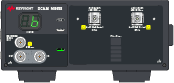
N1092C/E electrical channel specifications
| Item | Description |
|---|---|
| Electrical Channel Count | 2 (N1092C/E) |
| Electrical Input Connectors | 2.4 mm (m) bulkhead |
| Bandwidth, −3 dB (user selectable) | 20, 33, 40, and 50 GHz 1 |
| Transition Time (10% to 90% calculated from TR = 0.35/BW) | Description |
| 20 GHz BW | 17.5 ps (Calculated) |
| 33 GHz BW | 10.6 ps (Calculated) |
| 40 GHz BW | 8.8 ps (Calculated) |
| 50 GHz BW | 7.0 ps (Calculated) |
| Channel-to-Channel Skew Range | ± 100 ps |
| RMS Noise | Description |
| 20 GHz BW | 275 μV (Characteristic) |
| 33 GHz BW | 420 μV (Characteristic) |
| 40 GHz BW | 450 μV (Characteristic) |
| 50 GHz BW | 500 μV (Characteristic) |
| RMS Noise (Maximum) | 700 μV |
| Scale Factor (per division) | Description |
| Minimum | 1 mV/division |
| Maximum | 100 mV/division |
| DC Accuracy (VAVG Measurement) | ± 2 mV ± 4% (reading − offset) ± 1.15 mV (Characteristic) |
| DC Offset Range (referenced to center of screen) |
± 500 mV |
| Input Dynamic Range (relative to channel offset) |
± 400 mV |
| Maximum Input Signal | ± 2V (+16 dBm) |
| Nominal Input Impedance | 50 Ω |
Tuned to be −3 dB (±measurement uncertainty) at stated bandwidth(s) using NIST traceable swept-sine test system.
N1092A/B/C/D/E horizontal timebase specifications
| Item | Description |
|---|---|
| Scale Factor | Full scale is ten divisions |
| Minimum | 100 fs/div |
| Maximum | 100 μs/div |
| Sample Delay 1 | < 10 ns |
| Time Interval Accuracy (in pattern lock mode) |
± 0.3% of 1/(clock input frequency) or ± 1.2 ps (whichever is smaller) (Characteristic) 2 ± 150 fs ± 1% of 1/(clock input frequency) or ± 4 ps (whichever is smaller) 3 |
| Time Interval Accuracy (in clock trigger mode) |
± 0.3% of timespan or ± 1.2 ps (whichever is smaller) (Characteristic) 2 ± 150 fs ± 1% of timespan or ± 4 ps (whichever is smaller) 3 |
| Time Interval Resolution 4 | screen diameter / record length or 50 fs, whichever is larger |
| Jitter 5 | |
| Option STB | 400 fs rms (Characteristic) |
| 450 fs rms | |
| Option LOJ | 160 fs rms (Characteristic) |
| 200 fs rms | |
| Display Units | Bits or Time |
| Record length 6 | 16 to 131,072 without pattern lock, 1 to 268,435,456 with pattern lock and "Acquire Entire Pattern" |
| Sample rate 7 | |
| Standard | Up to 100 kHz |
| Option FS1 | Up to 250 kHz |
Time delay between the front panel clock input and when a sample is taken on the front panel channel input.
Dual marker measurement performed at a temperature within ± 1 °C of horizontal calibration temperature.
Dual marker measurement performed at a temperature within ± 5 °C of horizontal calibration temperature.
The time interval resolution is the smallest time spacing between two points.
Verified with a clock slew rate greater than 40V/ns and optical signal slew rate greater than 150 μW/ps.
Maximum number of samples depends on pattern, number of active channels, available memory, pattern lock enabled, and Acquire Entire Pattern enabled.
Each channel samples at the specified sample rate regardless of the number of channels.
N1092A/B/C/D/E clock input specifications
| Item | Description |
|---|---|
| Clock Input Non-destruct Voltage | 1.4 Vp-p |
| Clock Input Frequency | 500 MHz to 32 GHz |
| 100 MHz to 500 MHz (sub-rate clocks only, pattern lock off, provided that the data rate exceeds 500 Mb/s and the clock divide ratio is a power of two) | |
| Clock Input Sensitivity | 200 mVp-p |
| Minimum Clock Slew Rate | 0.5 V/ns |
| Nominal Input Impedance | 50 Ω (AC coupled) |
| Clock Input Connector | 2.92 mm (female) |
N1092A/B (Option 40A) clock recovery specifications
| Item | Description | |||
|---|---|---|---|---|
| Data Rates Input Range (Option CDR) | 24 GBd - 29 GBd | 48 GBd - 58 GBd | ||
| Data Rates Input Range (Option CRX) | 125 MBd to 64 GBd | |||
| Minimum Optical Modulation Amplitude (OMA) to achieve lock (Open eye) NRZ and PAM4 (OMA) 1310 nm/1550 nm, verified with clean open eye at 26.56 GBd and 53.125 GBd |
400 μW | |||
| 180 μW at 26.56 GBd (Characteristic) | ||||
| 250 μW at 53.125 GBd (Characteristic) | ||||
| PAM4 Stressed Eye 1310 nm/1550 nm (Clock recovery locks under these conditions) |
Baud Rate | Pattern | Outer OMA | TDECQ |
| 26.56 GBd | SSPRQ | –5.1 dBm (Characteristic) |
~3.4 dB (Characteristic) |
|
| 53.125 GBd | SSPRQ | –0.8 dBm (Characteristic) |
~3.4 dB (Characteristic) |
|
| Recovered Clock Out | Description | |||
| Amplitude | ≥ 200 mVpp | |||
| Divide ratio (user selectable) | 1, 2, 4, 8, 16, 32 | |||
| Front panel connector type and interface | 2.92 mm (m), 50 Ω, DC coupled | |||
| Random jitter | 280 fs maximum (≥ 2.5 GHz) 150 fs @ 26.56 GHz (Characteristic) |
|||
| Clock recovery adjustable loop bandwidth range (user selectable) |
0.5 MHz to 10 MHz (depends on Baud Rate) | |||
| Clock recovery loop peaking range | Up to 4 settings (dependent on loop BW) | |||
| Loop bandwidth accuracy 1, 2 | ± 30%, (Characteristic) | |||
| Acquisition range | ± 300 ppm, (Characteristic) | |||
| Maximum consecutive identical digits to lock | 150 (Characteristic) | |||
| Auto relocking | Yes (user enabled) | |||
| Internal frequency counter accuracy | ± 10 ppm 4 ppm (Characteristic) |
|||
| Clock Trigger Out (12.0 - 14.5 GHz) | Description | |||
| Amplitude | 700mVpp @ 13.28 GHz (Characteristic) | |||
| Frequency range | 8 - 16 GHz | |||
| Front panel connector type and interface | 2.92 mm (m), 50 Ω, DC coupled | |||
| Random jitter | 80 fs (Characteristic) | |||
PLL bandwidth is calibrated and verified using clean 26.5625 GBd and 53.125 GBd NRZ and PAM4 signals with FlexDCA clock recovery loop tuning enabled.
Actual PLL bandwidth may vary due to several factors, including pattern characteristics
(low/high transition density), signaling format (NRZ/PAM4), and signal quality (open/closed eyes).
N1092-series SIRC filter ranges
| Module/Option | Channel | Range1, 2 Min SIRC Freq. |
Range1, 2 Max SIRC Freq. |
|---|---|---|---|
| N1092A Option N28 | All Optical | 12.89 GBd (9.67 GHz) | 53.125 GBd (39.8 GHz) |
| N1092x Option 30A | All Optical | 12.89 GBd (9.67 GHz) | 53.125 GBd (39.8 GHz) |
| N1092x Option 40A | All Optical | 12.89 GBd (9.67 GHz) | 64 GBd (48 GHz) |
| N1092x Options 30A and 168 | All Optical | 8.4 GBd (6.3 GHz) | 53.125 GBd (39.8 GHz) |
Optical NRZ signals typically require a 4 pole Bessel filter at 75% of the data rate; Optical PAM 4 signals typically require a 4 pole Bessel filter at 50% of the data rate.
Only available with option IRC and compliance not guaranteed.
N1092A/B/C/D/E environmental specifications
| Item | Description | ||
|---|---|---|---|
| Use | Indoor | ||
| Temperature | Description | ||
| Operating | +10 °C to +40 °C (+50 °F to +104 °F) | ||
| Non-operating | −40 °C to +70 °C (−40 °F to +158 °F) | ||
| Altitude (Operating) | Up to 4,600 meters (15,000 ft) | ||
| Humidity 1 | Type tested at 95%, +40 °C (non-condensing) | ||
| Volts-Amperes (VA) (Characteristic) | Option 30A | Option 40A | Option CDR |
| N1092A | 48 VA | 48 VA | 70 VA |
| N1092B | 52 VA | 50 VA | 82 VA |
| N1092C | 52 VA | 52 VA | — |
| N1092D | 60 VA | 54 VA | — |
| N1092E | 52 VA | 54 VA | — |
| Weight (Characteristic) | Option 30A | Option 40A | Option CDR |
| N1092A | 6.0 kg (13.4 lb) | 6.0 kg (13.4 lb) | 6.8 kg (15 lb) |
| N1092B | 6.1 kg (13.6 lb) | 6.1 kg (13.6 lb) | 6.8 kg (15 lb) |
| N1092C | 6.1 kg (13.6 lb) | 6.1 kg (13.6 lb) | — |
| N1092D | 6.3 kg (14.0 lb) | 6.3 kg (14.0 lb) | — |
| N1092E | 6.1 kg (13.6 lb) | 6.1 kg (13.6 lb) | — |
| Dimensions | Description | ||
| Without front connectors and rear feet | 88.26 mm H x 207.40 mm W x 485 mm D (3.48 inch x 8.17 inch x 19.01 inch) |
||
| With front connectors and rear feet | 103.31 mm H x 219.56 mm W x 517.80 mm D (4.07 inch x 8.64 inch x 20.39 inch) |
||
| With front cover and rear feet | 110.18 mm H x 219.56 mm W x 550.71 mm D (4.34 inch x 8.64 inch x 21.68 inch) |
||
Samples of this product have been type tested in accordance with the Keysight Environmental Test Manual and verified to be robust against the environmental stresses of Storage, Transportation and End-use; those stresses include but are not limited to temperature, humidity, shock, vibration, altitude, and power line conditions. Test Methods are aligned with IEC 60068-2 and levels are similar to MIL-PRF-28800F Class 3.
N1092A/B/C/D/E LINE power specifications
| Item | Description |
|---|---|
| Voltage and/or range | 100–120 Vac, 50/60/400 Hz |
| 200–240 Vac, 50/60 Hz | |
| Power in Watts | 290 Watts Maximum |
| The products can operate with mains supply voltage fluctuations up to ± 10% of the nominal voltage. | |