N1094A/B Specifications
N1094A/B DCA-M multiple-channel electrical sampling oscilloscope specifications and characteristics apply when the temperature is within the range noted below. Use the DCA-M's rear panel USB Type B connector to connect the DCA-M to a DCA-X mainframe or to N1010A FlexDCA on a PC. The DCA-M is connected as a USB 2.0 device.
Minimum Firmware Version. The N1094A/B must be controlled from a PC (or 86100D) that is running a minimum FlexDCA firmware version of A.05.51 or higher. However, if the N1094A/B DCA-M, regardless of option, has a serial number ≥ MY62100101 FlexDCA firmware version A.06.90 or later is required. For additional information concerning the required firmware versions refer to DCA-M compatibility with N1000A and 86100D.
All specifications describe warranted performance over the temperature range +10C to + 40C (unless otherwise noted). The specifications are applicable after the temperature is stabilized, which occurs after 1 hour of continuous operation and within ±5C of the module's calibration temperature. Many performance parameters are enhanced through frequent, simple user calibrations.
Specifications describe warranted performance. Characteristics provide useful, nonwarranted information about the functions and performance of the instrument. Characteristics are printed in green italics. Characteristics are applicable after the temperature is stabilized, which occurs after 1 hour of continuous operation and within ±1C of the module's calibration temperature.
Nominal Value indicates the expected, but not warranted, value of the parameter.
Factory Calibration Cycle. For optimum performance, the N1094A/B should have a complete verification of specifications once every 12 months.
The Mains wiring and connectors shall be compatible with the connector used in the premise electrical system. Failure, to ensure adequate earth grounding by not using the correct components may cause product damage, and serious injury.
This product is designed for use in INSTALLATION CATEGORY II and POLLUTION DEGREE 2 environment.
N1094A/B electrical channel specifications
| Item | Description |
|---|---|
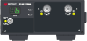
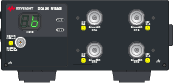
| Electrical Channel Count | 2 (N1094A) 4 (N1094B) |
| Electrical Input Connectors | 2.4 mm (m) bulkhead 1 |
| Bandwidth, 3 dB (user selectable) | Description |
| Option 030 | 20 GHz and 33 GHz 2 |
| Option 050 | 20 GHz, 33 GHz, 40 GHz, and 50 GHz 2 |
| Transition Time (10% to 90% calculated from TR = 0.35/BW) | Description |
| 20 GHz BW | 17.5 ps (Calculated) |
| 33 GHz BW | 10.6 ps (Calculated) |
| 40 GHz BW | 8.8 ps (Calculated) |
| 50 GHz BW | 7.0 ps (Calculated) |
| Channel-to-Channel Skew Range | ± 100 ps |
| RMS Noise | Description |
| 20 GHz BW | 275 μV (Characteristic) |
| 33 GHz BW | 420 μV (Characteristic) |
| 40 GHz BW | 450 μV (Characteristic) |
| 50 GHz BW | 500 μV (Characteristic) |
| RMS Noise (Maximum) | 700 μV |
| Scale Factor (per division) | Description |
| Minimum | 1 mV/division |
| Maximum | 100 mV/division |
| DC Accuracy (VAVG Measurement) | ± 2 mV ± 4% (reading − offset) ± 1.15 mV (Characteristic) |
| DC Offset Range (referenced to center of screen) |
± 500 mV |
| Input Dynamic Range (relative to channel offset) |
± 400 mV |
| Maximum Input Signal | ± 2 V (+16 dBm) |
| Input Impedance | 50 Ω (Characteristic) |
Option 030 is supplied with one 2.92 mm (f) to 2.40 mm (f), 50-Ohm 40 GHz adapter for each channel input.
Tuned to be –3 dB (± measurement uncertainty) at stated bandwidth(s) using NIST traceable swept-sine test system.
Clock input specifications
| Item | Description |
|---|---|
| Clock Input Non-destruct Voltage | 1.4 Vp-p |
| Clock Input Frequency | 500 MHz to 32 GHz (full rate or sub-rate clocks, pattern lock mode on or off) |
| 100 MHz to 500 MHz (sub-rate clocks only, pattern lock off, provided that the data rate exceeds 500 Mb/s and the clock divide ratio is a power of two) | |
| Clock Input Sensitivity | 200 mVp-p |
| Minimum Clock Slew Rate | 0.5 V/ns |
| Nominal Input Impedance | 50 Ω (AC coupled) |
| Clock Input Connector | 2.92 mm (female) |
Horizontal timebase specifications
| Item | Description |
|---|---|
| Scale Factor | Full scale is ten divisions |
| Minimum | 100 fs/div |
| Maximum | 100 μs/div |
| Sample Delay 1 | < 10 ns |
| Time Interval Accuracy (in pattern lock mode) |
± 0.3% of 1/(clock input frequency) or ± 1.2 ps (whichever is smaller) (Characteristic) 2 ± 150 fs ± 1% of 1/(clock input frequency) or ± 4 ps (whichever is smaller) 3 |
| Time Interval Accuracy (in clock trigger mode) |
± 0.3% of timespan or ± 1.2 ps (whichever is smaller) (Characteristic) 2 ± 150 fs ± 1% of timespan or ± 4 ps (whichever is smaller) 3 |
| Time Interval Resolution 4 | screen timespan / record length or 50 fs, whichever is larger |
| Jitter 5 | Description |
| Option STB | 400 fs rms (Characteristic) |
| 450 fs rms | |
| Option LOJ | 135 fs rms (Characteristic) |
| 160 fs rms | |
| Display Units | Bits or Time |
| Record length 6 | 16 to 131,072 without pattern lock, 1 to 268,435,456 with pattern lock and "Acquire Entire Pattern" |
| Sample rate 7 | Description |
| Standard | 100 kHz |
| Option FS1 | 250 kHz |
Time delay between the front panel clock input and when a sample is taken on the front panel channel input.
Dual marker measurement performed at a temperature within ± 1 °C of horizontal calibration temperature.
Dual marker measurement performed at a temperature within ± 5 °C of horizontal calibration temperature.
The time interval resolution is the smallest time spacing between two points.
Verified with a clock and signal slew rate greater than 45 mV/ps.
Maximum number of samples depends on pattern, number of active channels, available memory, pattern lock enabled, and Acquire Entire Pattern enabled.
Each channel is sampled at the specified sample rate regardless of the number of active channels.
Environmental specifications
| Item | Description |
|---|---|
| Use | Indoor |
| Temperature | Description |
| Operating | +10C to +40C (+50 °F to +104 °F) |
| Non-operating | −40C to +70C (−40 °F to +158 °F) |
| Altitude (Operating) | Up to 4,600 meters (15,000 ft) |
| Humidity 1 | Type tested at 95%, +40 °C (non-condensing) |
| Volts-Amperes (VA) (Characteristic) | Description |
| N1094A | 48 VA |
| N1094B | 52 VA |
| Weight (Characteristic) | Description |
| N1094A | 6.0 kg (13.4 lb) |
| N1094B | 6.1 kg (13.6 lb) |
| Dimensions | Description |
| Without front connectors and rear feet | 88.26 mm H x 207.40 mm W x 485 mm D (3.48 inch x 8.17 inch x 19.01 inch) |
| With front connectors and rear feet | 103.31 mm H x 219.56 mm W x 517.80 mm D (4.07 inch x 8.64 inch x 20.39 inch) |
| With front cover and rear feet | 110.18 mm H x 219.56 mm W x 550.71 mm D (4.34 inch x 8.64 inch x 21.68 inch) |
Samples of this product have been type tested in accordance with the Keysight Environmental Test Manual and verified to be robust against the environmental stresses of Storage, Transportation and End-use; those stresses include but are not limited to temperature, humidity, shock, vibration, altitude and power line conditions. Test Methods are aligned with IEC 60068-2 and levels are similar to MIL-PRF-28800F Class 3.
N1094A/B LINE power specifications
| Item | Description |
|---|---|
| Voltage and/or range | 100–120 Vac, 50/60/400 Hz |
| 200–240 Vac, 50/60 Hz | |
| Power in Watts | 290 Watts Maximum |
| The products can operate with mains supply voltage fluctuations up to ± 10% of the nominal voltage. | |