86116B Module Specifications
86116B module specifications and characteristics apply when a module is installed in the instrument mainframe. The following notes refer to the module specifications listed in this chapter.
All specifications describe warranted performance over the temperature range +10° C to + 40° C (unless otherwise noted). The specifications are applicable after the temperature is stabilized, which occurs after 1 hour of continuous operation and while module calibration is valid. Many performance parameters are enhanced through frequent, simple user calibrations.
Specifications describe warranted performance. Characteristics provide useful, nonwarranted information about the functions and performance of the instrument. Characteristics are printed in green italics.
Factory Calibration Cycle. For optimum performance, the instrument should have a complete verification of specifications once every 12 months.
Nominal Value indicates the expected, but not warranted, value of the parameter.
| Item | Description |
|---|---|
| Wavelength Range | 1480 – 1620 nm |
| Calibrated Wavelength | 1550 nm |
| Optical Channel Bandwidth. Calculated from optical impulse pulse width measurements on an optical impulse: BW = 0.48/FWHM. | |
| Best Pulse Fidelity Mode | 65 GHz (characteristic-calculated) |
| Better Sensitivity Mode | ~ 60 GHz (characteristic-calculated) |
| Best Sensitivity Mode | ~ 55 GHz (characteristic-calculated) |
| Default Optical Channel Setting | 65 GHz (best pulse fidelity mode) |
| Impulse Rise Time | 5.4 ps. (10% to 90% measured from impulse response) |
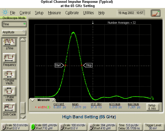
| Impulse Pulse Width | 7.4 ps (characteristic) |
Measured with optical impulse (Best Pulse Fidelity Mode) with a pulse of 700 fs FWHM, 5 MHz repetition rate, and 10 mW peak power. System jitter less than 800 fs RMS. Refer to following graphic. |
|
| Impulse Distortion | < 10% (characteristic)
Impulse distortion (%) = [(distortion peak-to-peak)/impulse height] x 100%. |
| Average Input Power for Linear Operation using 40 Gb/s RZ Signals | < 5 mW (characteristic). Tested with 40 Gb/s RZ signals with pulses of 6 ps (FWHM). |
| Polarization Dependent Loss (PDL) | < 0.8 dB (characteristic) |
| RMS Noise. Measured one standard deviation from mean, with modules set at 1310 nm O/E conversion (responsivity) mode. | |
| 65 GHz Setting (best pulse fidelity) | 250 μW, maximum
140 μW, characteristic |
| 60 GHz Setting (better sensitivity) | 150 μW, maximum
70 μW, characteristic |
| 55 GHz Setting (best sensitivity) | 85 μW, maximum
50 μW, characteristic |
| Scale Factor (full height is eight divisions) | |
| Minimum | 200 μW/division |
| Maximum | 5 mW/division |
| CW Optical Power Accuracy | ±150 μW ±4% of (reading – channel offset) Single marker, referenced to average power monitor. |
| CW Optical Power Offsetre | –12 mW to + 8 mW Referenced two divisions from screen bottom. |
| Average Optical Power Monitor (1480 – 1620 nm) |
–23 dBm to +9 dBm (5 μW to 8 mW) |
| Average Optical Power Factory Calibrated Accuracy | ±5% ± 100 nW ± connector uncertainty, 20°C to 30°C Conditions: CW optical power only (no modulation) |
| Average Optical Power User Calibrated Accuracy | ±3.5% ± 100 nW ± power meter uncertainty, ± connector uncertainty, < 5°C change. Conditions: CW optical power only (no modulation) |
| Maximum Input Average Optical Power | |
| Maximum Displayed Peak | 40 mW (+16 dBm) |
| Maximum Linear Peak | 30 mW (+14.8 dBm), or 0.15 pJ per pulse, whichever is less. (characteristic) |
| Maximum Non-destruct Peak | 50 mW (+17 dBm), or 0.25 pJ per pulse, whichever is less. (characteristic) |
| Maximum Non-destruct average | 10 mW (+10 dBm). (characteristic) |
| Maximum non-destruct power is related to the fill factor (duty cycle) of the RZ waveform. The factory specification is defined by using a 20% filled 40 Gb/s pulse train (in other words, 5 ps FWHM and 25 ps period). This concept can also be specified as maximum non-destruct pulse energy. The factory specification is specified with 5 ps FWHM optical pulses and maximum non-destruct power providing that the individual pulse shape is square. | |
| Fiber Input | 9/125 μm |
| Connector for fiber input | User-selectable. |
| Input Return Loss | 20 dB With HMS-10 connector fully filled fiber. Proper connector care is required to maintain this specification. |
| Item | Description |
|---|---|
| Electrical Channel Bandwidth | |
| Best Pulse Fidelity | 80 GHz (warranted) (90 GHz characteristic) |
| Better Sensitivity | ~55 GHz (characteristic) |
| Best Sensitivity | ~30 GHz (characteristic) |
| Default Electrical Channel Setting | 80 GHz (Best Fidelity Mode) |
| Specified with a 3.2 GHz moving average. | |
| Transition Time (10% to 90%) Calculated from tr = 0.35 / BW. | |
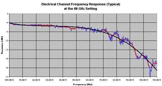
| 80 GHz setting Refer to following graphic. |
4.4 ps (characteristic-calculated) |
| 55 GHz setting | 6.4 ps (characteristic-calculated) |
| 30 GHz setting | 11.7 ps (characteristic-calculated) |
The blue curve is the unfiltered data, the red curve is the filtered data, and the black curve is a curve fit. |
|
| RMS Noise | |
| 80 GHz Setting (best pulse fidelity) | 2.2 mV, maximum
1.1 mV, characteristic |
| 55 GHz Setting (better sensitivity) | 1.4 mV, maximum
0.6 mV, characteristic |
| 30 GHz Setting (best sensitivity) | 0.8 mV, maximum
0.5 mV, characteristic |
| Measured one standard deviation from mean. | |
| Scale Factor (full height is eight divisions) | |
| Electrical Minimum | 2 mV/division |
| Electrical Maximum | 100 mV/division |
| dc Accuracy (single marker) | |
| 80 GHz Setting | ±0.4% of full scale ± 3 mV ± 4% of (reading – channel offset) ±2% of offset |
| 55 GHz Setting | ±0.4% of full scale ± 3 mV ± 2% of (reading – channel offset) ±2% of offset |
| 30 GHz Setting | ±0.4% of full scale ± 3 mV ± 2% of (reading – channel offset) ±2% of offset |
| Offset Range (referenced to center of display graticule) | ±500 mV |
| Input Dynamic Range (relative to channel offset) | ±400 mV |
| Maximum Input Signal | ± 2Vdc (+16 dBm) |
| Nominal Impedance | 50 ohm |
| Return Loss (characteristic) | > 10 dB from DC to 70 GHz > 7 dB from 70 to 100 GHz |
| Electrical Input Connector | 1.85 mm, Male |