PWA Channel Setup
Use this Setup dialog to configure N1060A and 86108A/B precision waveform analyzer modules.
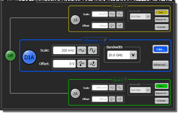
Channels
The precision waveform analyzer has two electrical channels. Click the channel buttons  in the dialog to display or hide a channel's waveform on the display. For each channel, adjust the waveform's Scale and vertical Offset. Scale set the channel's sensitivity (volts-per-division), with vertical expansion and contraction is about the center offset value of the display.
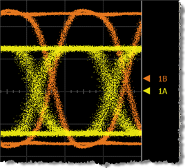 A waveform's Offset is identified by a ground marker (
 ). This marker is located on the display's right side, has the same color as the associated waveform, and identifies the location of 0V. Each channel has its own ground marker. The default marker position is middle screen for electrical channels. During an Auto Scale, an offset is applied to vertically center the signal. The offset changes the vertical position of the waveform on the display screen without modifying the waveform itself. The offset value represents an absolute value on the instrument display. The amount of offset applied is shown on the Channel button. You can also quickly change a waveform's vertical offset by using the pointing device to vertically drag the ground marker ( ) on the display.
The Bandwidth setting affects the width of the sampling pulse used by the oscilloscope:
- Wider bandwidths allow the oscilloscope to respond to fast changes in a waveform. The increased bandwidth then yields the highest measurement fidelity.
- Narrow bandwidths offer the best sensitivity by reducing the noise on the input waveform while still maintaining good frequency response. A lower sampler bandwidth is especially useful for low-level signals that cannot be averaged.
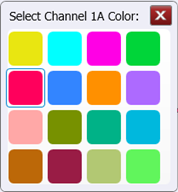
Waveform Color
Click the Color button to display the waveform in one of 16 colors.
External Hardware
Click External HW to compensate for an external transducer or external attenuator in the test setup. External hardware scaling is available for both electrical and optical channels. If a probe has been configured for the channel, information for the probe is also presented.
Advanced
Click the Advanced button to apply Horizontal Software Delay.
Differential Waveform
 Click the Diff button to view a differential waveform of the two channels. All three waveforms can be simultaneously viewed. In differential mode, you can click one of three Advanced buttons. The button for the individual channels allows you to apply hardware skew and software delay. The Advanced button for the differential waveform allows you to apply horizontal software delay and enable automatic scaling.