PWA Precision Timebase Setup
Use this Setup dialog to configure N1060A and 86108A/B precision waveform analyzer modules.
Precision Timebase
Use the Setup dialog's Precision Timebase tab to configure and turn on the precision timebase. A precision timebase provides an alternate N1000A's timebase source (clock) that greatly improves jitter performance and timebase linearity. Sampling is random with the precision timebase and the timing of each random sample is precisely identified. Both N1060A and 86108A/B modules include a front-panel port to connect an external clock.
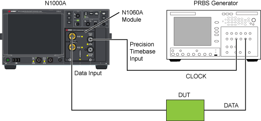
In the following figure, the clock is connected to the N1060A's Precision Timebase Input. In the N1060A Setup dialog's Precision Timebase tab, set the Reference Source to External. In the Trigger Setup dialog's General Trigger Setup tab, set the Source to Automatic. Click Setup > Trigger to open the Trigger Setup dialog.
Figure. Setup for Internal Precision Timebase with N1060A
Precision Timebase and Trigger Connections from an N107x-Series DCA-M
When using an N107x-series DCA-M clock recovery module with an N1060A or 86108A/B, know that the signal from the N107x's Aux Clock Out connector has significantly lower jitter than the signal from the N107x's Recovered Clock Out connector. Therefore:
- Connect the N107x's Aux Clock Out (lower jitter) to the DCA-X's or N1060A's Precision Timebase Input, and
- Connect the N107x's Recovered Clock Out to the DCA-X's Trigger Input.
Avoid damaging the front-panel Precision Timebase Input. Do not use a reference clock greater than ±2V (16 dBm) maximum.
Reference Source Settings
Select whether to use the Internal or an External reference clock. For either selection, make the required connections as shown in the above figure. When the precision timebase is used, the instrument does not normally use a trigger, and the reference clock is connected directly to the precision waveform analyzer's front-panel Precision Timebase Reference Input (or, External Time Ref In on 86108As). You can also use the oscilloscope in Free Run mode with this setup.
If pattern lock is turned on or Jitter Mode is used, connect the reference clock to both the precision waveform analyzer's front-panel input and to the oscilloscope's front-panel Trigger Input.
The input requires a full or sub-rate reference clock signal (square wave, BERT output, or a sine wave) from:
- 1 to 18 GHz for the N1060A
- 1 to 16 GHz for the 86108B
- 2 to 13.5 GHz for the 86108A
If the edges of the clock are too fast for a reliable reference, you may need to add an external low-pass filter or additional cable length to soften the edges.
When the precision timebase is configured to use an external reference, the clock data recovery circuitry is disabled.
Reference Clock Frequency Settings
When an External clock source is selected, use the Reference Clock Frequency field to enter the frequency of the external synchronous clock. This is the frequency at the input to the module. You must specify the reference clock frequency to ensure that absolute time measurements are accurate. Each frequency in the list is associated with a standard symbol rate. Click Select From List to select from a list of standard optical and digital telecommunications rates. This list is also available in the Pattern Lock Setup tab of the Trigger dialog. FlexDCA determines the phase of a data sample within one period.
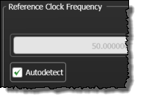 When an External clock source is selected and pattern lock is turned on, the Autodetect check box is displayed as shown in this picture. When selected, an Auto Scale automatically detects the external reference frequency. With pattern lock on, the instrument may be unable to correctly detect an external reference frequency. If this happens, clear the Autodetect check box.
PRBS data is not a suitable reference clock signal.
To ensure accuracy, the entered reference clock frequency must equal the actual external reference clock. Any deviations in either frequency will result in an inaccurate timebase. The instrument will display a warning message on the screen if the time reference is not valid. You must ensure that you connect a valid reference clock. If the precision timebase is on, you can perform an Auto Scale to reset the time reference.
This field is not displayed if you select an Internal reference source.
Timebase Control Settings
 Select Enable Precision Timebase to enable or disable the precision timebase. The Precision Timebase button's green indicator
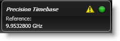
  (on the button toolbar) indicates when the precision timebase is on. If the yellow warning indicator
  is shown, the time reference is not set or the signal is not connected to the 86108A/B's front'panel connector. If any changes in the reference clock occur, click Reset Time Reference to reset the precision timebase. The time reference will fail if:
If any changes in the reference clock occur, click Reset Time Reference to reset the precision timebase. The time reference will fail if:
- Reference clock signal is not:
- Valid frequency range
- Too large or too small
- DC offset > ±200 mV
- unstable frequency or amplitude
- A setup, in which the precision timebase was enabled when saved, is recalled
- Instrument power is turned on when the state of the precision timebase was enabled at instrument power off
Synchronization Method Settings
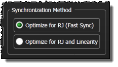
By default, precision timebase synchronization optimizes for RJ (Random Jitter) only. This provides a fast synchronization that is suitable for analysis of most signals. Optionally, you can choose to optimize both for RJ and for timebase linearity. This type of synchronization takes much longer but results in an extremely linear timebase as well as the lowest possible RJ. This type of synchronization is suggested for signals with extremely low DJ (Deterministic Jitter), where the signal rate is a multiple of the precision timebase reference frequency. For example, if your Data Rate is 32 GBd while your precision timebase reference frequency is 8 GHz, this option may improve the accuracy of the DJ measurements.
To ensure accuracy, you must set the reference clock frequency and the external reference clock to the same frequency. Any deviations in either frequency will result in an inaccurate timebase. The instrument will display a warning message on the screen if the time reference is not valid. You must ensure that you connect a valid reference clock.
If the precision timebase is on, you can perform an Auto Scale to reset the time reference.
Status
The Status area of the dialog provides the following messages:
- Precision Timebase Off. The precision timebase is disabled. The time reference will be invalid until the precision timebase is enabled.
- No Time Reference. The precision timebase is enabled; however, the time reference is invalid. This status appears after changing the frequency band of the reference clock signal or recalling an instrument setup.
- Time Reference Set. The precision timebase is enabled and the time reference is valid.
- Time Reference Lost. The precision timebase is enabled. The instrument continues to acquire data using the most recent time reference. This status follows an absent reference clock signal, a clock signal that is too large (or too small), a clock signal that is not in a valid frequency band, or a clock signal that does not have a stable frequency.
Select the Show Precision Timebase Signals field to view the In Phase Waveform and Quadrature Waveform inputs to the precision timebase circuitry. Both an amplitude-vs-time chart and a Lissajous Pattern chart are displayed. This feature provides a qualitative view of the inputs. There is no remote command for making this selection. However, you can use the :WAVeform:SOURce command documented in the FlexDCA Programmer's Guide to return the two waveforms.