N1077A Optical CDR Test Setups
The illustrations in this topic represent a variety of optical clock recovery using the N1077A. In some situations, the length of the cables used can impact measurement accuracy. For more information, download the N107x-series user's guide at www.keysight.com.
Circled numbers in this figure identify items from the electrical phase matching kits. Optional equalizers can be added to open a closed eye for clock recovery.
Precision Timebase and Trigger Connections from an N107x-Series DCA-M
When using an N107x-series DCA-M clock recovery module with an N1060A or 86108A/B, know that the signal from the N107x's Aux Clock Out connector has significantly lower jitter than the signal from the N107x's Recovered Clock Out connector. Therefore:
- Connect the N107x's Aux Clock Out (lower jitter) to the DCA-X's or N1060A's Precision Timebase Input, and
- Connect the N107x's Recovered Clock Out to the DCA-X's Trigger Input.
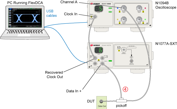
Example Setup 1. Single-Ended Input, N1077A-SXT, DCA-M Scope
This example setup shows an N1077A-SXT connected to an N1094B oscilloscope with a single-ended electrical input signal. The microwave pickoff is used to tap a portion of the input signal as an input to the clock recovery module.
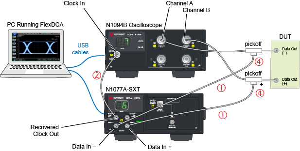
Example Setup 2. Differential Input, N1077A-SXT, DCA-M Scope
This example setup shows an N1077A-SXT connected to an N1094B oscilloscope with a differential input signal. Two microwave pickoffs are used to tap a portion of the input signal as an input to the clock recovery module.
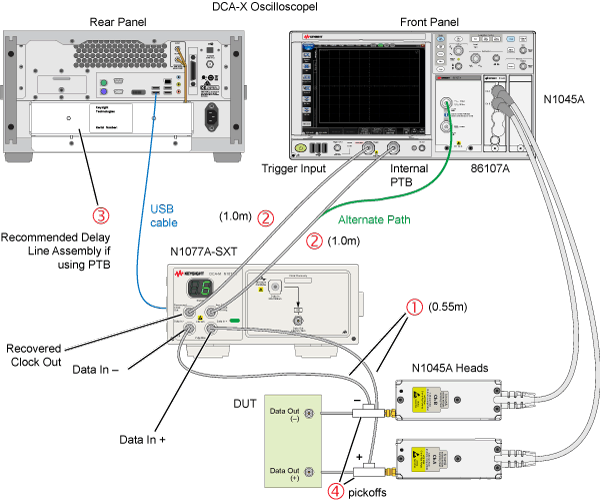
Example Setup 3. Differential Input, N1077A-SXT, DCA-X Scope
This example setup shows an N1077A-SXT connected to a DCA-X oscilloscope. The oscilloscope has an N1045A receiver module and an 86107A precision timebase.
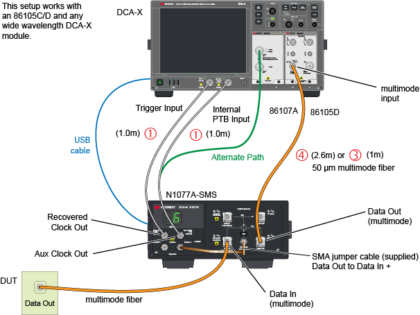
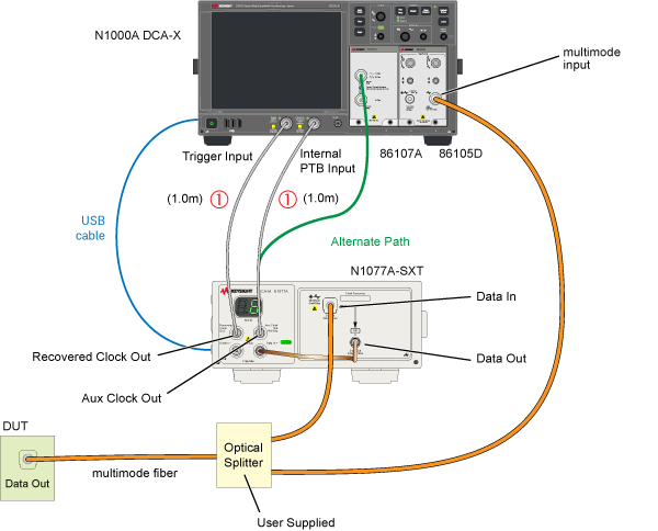
Example Setup 4. Multimode Input, N1077A-SXT, External Splitter
This example setup shows an N1077A connected to a DCA-X oscilloscope. The oscilloscope has an 86105D receiver module which has a multimode optical input connector. Since the N1077A-SXT does not have an internal optical splitter, the user must supply their own.
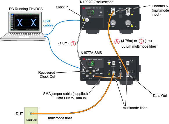
Example Setup 5. Single-Mode Input, N1077A-SMS, DCA-M Scope
This example setup shows an N1077A-SMS connected to an N1092E oscilloscope. Single-mode fiber can be connected to the N1077A-SMS’s single-mode input connector. Since the N1092-series oscilloscopes do not have a single-mode input, you can use a multimode patchcord in most cases.
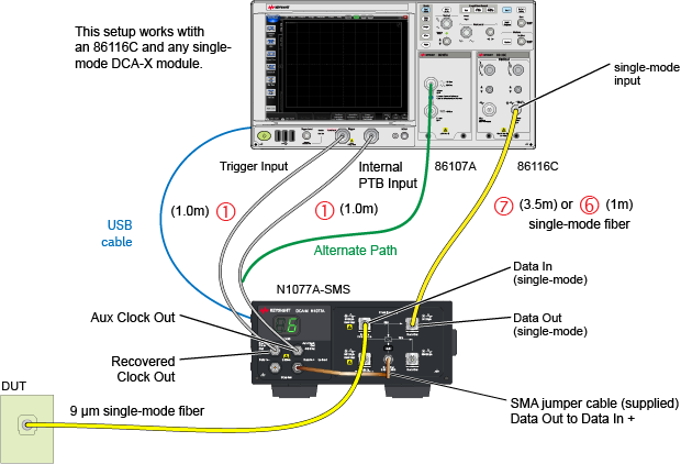
Example Setup 6. Single-Mode Input, N1077A-SMS, 86116C
This example setup shows an N1077A-SMS connected to a DCA-X oscilloscope with an 86116C.
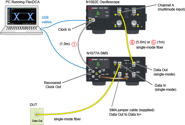
Example Setup 7. Multimode Input, N1077A-SMS, DCA-M Scope
This example setup shows an N1077A-SMS connected to an N1092E oscilloscope.
Example Setup 8. Multimode Input, N1077A-SMS, 86105D
This example setup shows an N1077A-SMS connected to a DCA-X oscilloscope that has an 86105D module installed (multimode input).