Connecting DCA-Ms
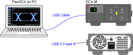
This procedure shows you how to connect any DCA-M oscilloscope or DCA-M clock recovery extended module to a DCA-X or to FlexDCA application installed on a PC.
Safety of any system incorporating the equipment is the responsibility of the assembler of the system.
To connect FlexDCA to a DCA-M
- Turn the DCA-M power on and connect a USB 2.0 type A to Type B cable where the Type B plug is connected to the DCA-M's rear-panel Type B receptical which is shown in the following picture. Be aware that USB Type B connectors for USB 2.0 and 3.0 have different shapes.
- Click Setup > Configure Extended Modules. Or, click the
 icon that is displayed to the right of the channel buttons along the bottom of the display.
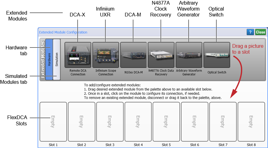
 - In the Extended Module Configuration dialog, click the Hardware tab.
- The DCA-M should be automatically detected. In the unlikely event that the DCA-M connection is not automatically detected, unplug the DCA-M's USB cable, wait a few moments, and plug the cable back in. The DCA-M picture will be visible in one of the FlexDCA Slots shown in the following picture. On FlexDCA on a DCA-X, slots 1 through 4 are permanently assigned to the physical DCA-X slots. Slots 5 through 8 can be assigned to simulated modules or supported external instruments.
Alternate Connection Method
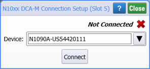
- Click on the DCA-M picture that you dragged to a FlexDCA Slot in the above procedure. The picture should be in one of FlexDCA's slots. This brings up the N10xx DCA-M Connection Setup dialog.
- In the dialog, confirm that Device identification string correctly lists the DCA-M's
<model>–<serial number>similar to what is shown in this picture. If not, enter the correct values and click Connect.
If N1010A FlexDCA is currently connected to a DCA-X, the DCA-M must be connected to the PC. In this configuration, the extended DCA-M module cannot be connected to the DCA-X.