N107X-Series Installation
This example shows an N1077A-SMS that is connected to an N1092D-series sampling oscilloscope. Connecting a different N107X-series or N109X-seris DCA-M is similar. If you are using an N1077A-SXT, you will need an external optical splitter. If you are using an electrical clock recovery module, you will connect your electrical data signal to the front-panel Data In + port.
The input Clock In signal must be a synchronous clock or sub-rate clock. However, the DCA-M will trigger with any clock signal within the range specified in the FlexDCA help system. For this procedure, the following assumptions are made for simplicity. You can set these parameters to any acceptable values:
- Data signal: 10.3125 GBd
- N1092D DCA-M slot: 5
- N107X-series DCA-M slot: 6
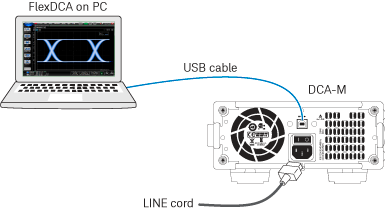
The PC (not provided by Keysight) is running the N1010A FlexDCA software. FlexDCA controls the N1090A over a USB 2.0 connection. The USB cable provided with the N109X-series is a USB-A plug to right-angle USB-B plug.
- Using the USB cable, connect the N1092D to the PC. If connecting to an N1000A, be sure to connect the USB cable to an N1000A rear-panel USB port.
- Connect the line cord to the N1092D and N107X-series DCA-M and turn them on. Device drivers automatically recognize the DCA-Ms and establish a connection. The device driver is automatically installed when FlexDCA is installed on the PC.
- Connect the N107X-series DCA-M and N1092D as shown in the following picture. Connect an optical signal to be measured to the N1092D's front-panel fiber-optic connector.
- Connect the recovered Recovered Clock Out signal to the N1092D's front-panel Clock In SMA connector.
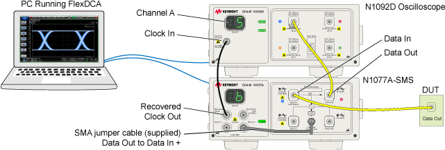
When using an N107x-series DCA-M clock recovery module with an N109x DCA-M, know that the signal from the N107x's Aux Clock Out connector has significantly lower jitter than the signal from the N107x's Recovered Clock Out connector. Therefore, if possible connect, it is recommended to connect the N107x's Aux Clock Out (lower jitter) to the N109x's Clock In connector.
Configure clock recovery
- In FlexDCA, click Setup > Trigger Setup and select the General Trigger Setup tab. Confirm that the trigger Source is set to Front Panel.
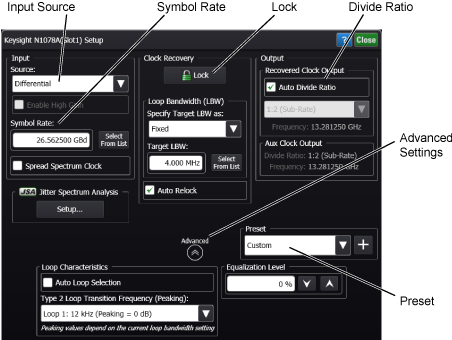
- Click Setup > Modules > (Slot 6): Clock Recovery to view the Setup dialog.
- For the Input Source, select Electrical Data +, which is used for single-ended or optical signal.
- In the Data Rate field, enter 10.3125 GBd.
- In the Clock Recovery field, click the Lock button to lock clock recovery. The N107X-series DCA-M's front-panel locked light should be green. If not, confirm the oscilloscope is in Run mode.
Configure N109X-series oscilloscope
- In FlexDCA’s signals palette, turn all channels off except for channel 5A.
- Click Run.
- Click Setup > Mode > Eye/Mask.
- Click Auto Scale.
- The N109X-series oscilloscope’s front-panel Trig’d light should be green. If not, confirm that the amplitude of the signal at channel 5A is not too low due to the “pass through” loss in the N1077A. Consult the specifications listed in the oscilloscope user’s guide.
Configure pattern lock (optional)
- The N109X-series oscilloscope must have option PLK.
- Click Setup > Trigger Setup and select the Pattern Lock tab. In the Data Rate field, turn off Auto Detect and select 10.3125 GBd.
- In the General Setup tab, click the Pattern Lock button.