N1077B Optical CDR Test Setups
The illustrations in this topic represent a variety of optical clock recovery using the N1077B. In some situations, the length of the cables used can impact measurement accuracy. For more information, download the N107x-series user's guide at www.keysight.com.
Circled numbers in this figure identify items from the electrical phase matching kits. Optional equalizers can be added to open a closed eye for clock recovery.
Precision Timebase and Trigger Connections from an N107x-Series DCA-M
When using an N107x-series DCA-M clock recovery module with an N1060A or 86108A/B, know that the signal from the N107x's Aux Clock Out connector has significantly lower jitter than the signal from the N107x's Recovered Clock Out connector. Therefore:
- Connect the N107x's Aux Clock Out (lower jitter) to the DCA-X's or N1060A's Precision Timebase Input, and
- Connect the N107x's Recovered Clock Out to the DCA-X's Trigger Input.
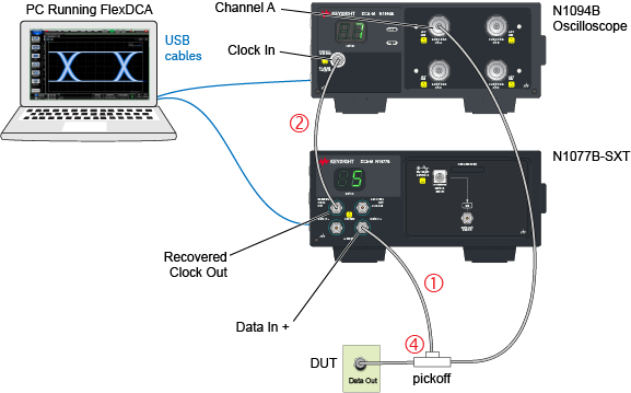
Example Setup 1. Single-Ended Input, N1077B-SXT, DCA-M Scope
This example setup shows an N1077B-SXT connected to an N1094B oscilloscope with a single-ended electrical input signal. The microwave pickoff is used to tap a portion of the input signal as an input to the clock recovery module.
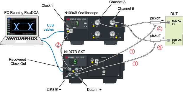
Example Setup 2. Differential Input, N1077B-SXT, DCA-M Scope
This example setup shows an N1077B-SXT connected to an N1094B oscilloscope with a differential input signal. Two microwave pickoffs are used to tap a portion of the input signal as an input to the clock recovery module.
Example Setup 3. Differential Input, N1077B-SXT, DCA-X Scope
This example setup shows an N1077B-SXT connected to a DCA-X oscilloscope with a differential input signal. The oscilloscope has an N1045A receiver module and an 86107A precision timebase. Two microwave pickoffs are used to tap a portion of the input signal as an input to the clock recovery module.
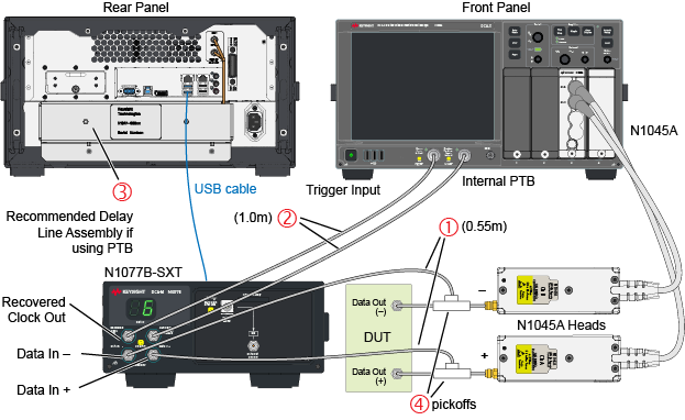
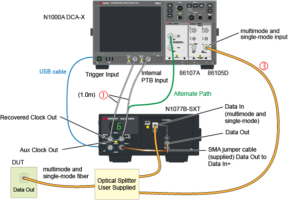
Example Setup 4. Single-Mode Input, N1077B-SXT, 86105D
This example setup shows an N1077B-SXT connected to a DCA-X oscilloscope. The oscilloscope has an 86105D receiver module which has a multimode optical input connector. The N1077B has single-mode optical input connector. Since the N1077B-SXT does not have an internal optical splitter, the user must supply their own.
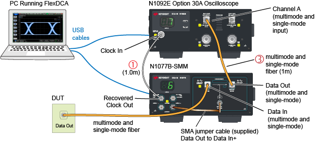
Example Setup 5. Single-Mode Input, N1077B-SMM, DCA-M Scope
This example setup shows an N1077B-SMM connected to an N1092E oscilloscope. Single-mode fiber is connected to the N1077B-S50’s single-mode input connector. Since the N1092-series oscilloscopes has a multimode input, you can use a multimode patchcord in most cases.
Using N1077B option SMM with N1092x option 40A is not recommended due to the high loss path between the N1077B's Data Out connector (50 μm) and N1092x option 40A's Channel input connector (9 μm).