N1078A 56 Gbaud Optical/Electrical CDR
 N1078A optical/electrical clock recovery takes an incoming data or clock signal, locks onto it using a phase-locked loop (PLL) circuit, and outputs a recovered clock. The recovered clock can be used as a timing reference for oscilloscopes (like the N1000A and N1090A, N1092-series, and N1094-series DCA-M oscilloscopes) or BERTS.
The N1078A works with both NRZ and PAM4 signals. With optional external hardware equalizers (such as provided in the N1027A-76A kit), you can perform "closed eye" measurements. For installation, safety, and regulatory information, refer to the N107X-series user's guide which can be downloaded from www.keysight.com.
Clock recovery is often required for:
- Standards compliance
- Clock-less devices
- Excessive clock-to-data delay such as is introduced by long spools of fiber-optic cable.
This module requires FlexDCA firmware version A.05.80 or above.
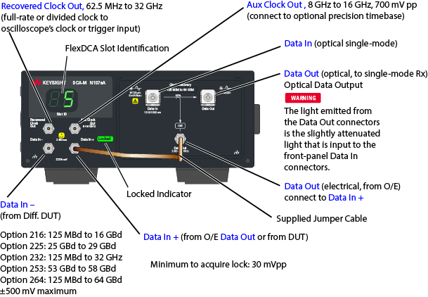
N1078A-S50 Front Panel (internal single-mode splitter)
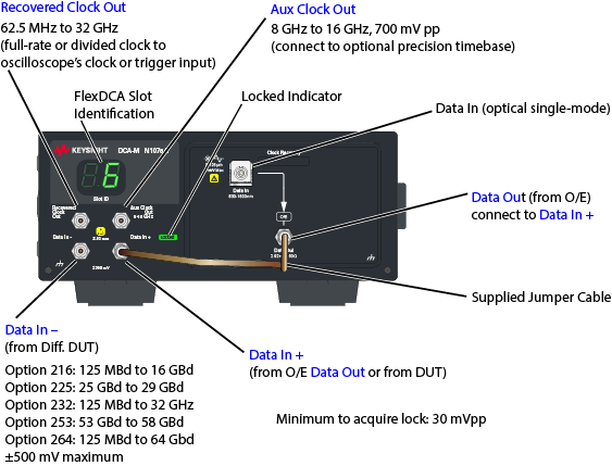
N1078A-SXT Front Panel (no internal splitter)
| Indicator | Description |
|---|---|

|
Displays the FlexDCA extended module slot where the N1078A is installed. |

|
Locked light is green when the N1078A is locked on the input signal. |
| Data In – and Data In + port (electrical) | These are the single-ended and differential data inputs from which to recover the clock. Use a splitter to divert part of the data signal to clock recovery and part of the signal to the oscilloscope's channel input. |
| Data In port (optical) | This optical input signal that is connected to this port is converted to an electrical signal at the electrical Data Out connector. On N1078A-S50 instruments, a slightly attenuated light is output from the optical Data Out connectors. See the warning below. Use the supplied jumper cable to connect the signal at the electrical Data Out connector to the front panel Data In + connector. |
| Data Out port (electrical) | Electrical data signal converted from the optical that is input at the optical Data In port. Use the supplied jumper cable to connect the electrical signal at this connector to the front panel Data In + connector. |
| Data Out N1078A-S50 port (optical) | Normally, this N1078-S50 output would be connected to the oscilloscope's channel input connector.
The light emitted from the N1078A-S50 optical Data Out connectors is the slightly attenuated light that is input to the front-panel Data In connectors. |
| Recovered Clock Out | Connect this output to the oscilloscope's clock or trigger input. Output frequency range is dependent on option. |
| Aux Clock Out | An auxilliary recovered clock output from 8 GHz to 16 GHz. |
| Port | Description |
|---|---|
| USB connector | Use the provided USB cable to connect this port to an DCA-X's or PC's USB connector. |
| LINE power on/off switch | Use this switch to turn the N1078A on and off. |
| LINE power input | Refer to the N107X-series user's guide for LINE power specifications. This PDF can be downloaded from www.keysight.com. |
To Safely Perform Optical Clock Recovery Using DCA-M Modules
When performing optical clock recovery, always select the Enable High Gain setting on N1077B and N1078A DCA-M modules that support this feature.
Avoid damaging DCA-M modules when performing clock recovery on optical signals by performing the following steps in the order given.
To setup optical clock recovery
- In the module's Setup dialog, select the Clock Recovery tab. In the tab Input field, select the clock recovery input source to be optical.
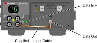
- Connect the jumper cable between the electrical Data Out and Data In + connectors as shown in the following figure.
- In the Input field of the Setup dialog's Clock Recovery tab, the Select Enable High Gain.
Always enable high gain after performing steps 1 and 2.
If the Clock Recovery tab does not include the Enable High Gain setting, you can safely omit this step as this feature is not supported on the DCA-M module that you are using.
To turn off optical clock recovery
- Clear the Enable High Gain, setting or press Setup > Default Setup.
- Remove the jumper cable.
General Cautions
Never exceed maximum optical input signal power to the Data In connector regardless of the state of the Enable High Gain setting. Failure to observe this caution will result in damage to the instrument.
Before selecting Enable High Gain, always connect the supplied semi-ridged jumper cable between the electrical Data Out and Data In + connectors. Failure to observe this caution may result in damage to the instrument.
Always clear Enable High Gain before disconnecting the supplied semi-ridged jumper cable between the electrical Data Out and Data In + connectors. Failure to observe this caution may result in damage to the instrument.
When Enable High Gain is selected, never connect an electrical cable to the electrical Data In + connectors except for the supplied semi-ridged jumper cable which connects the intstrument's Data Out and Data In + connectors. Failure to observe this caution may result in damage to the N1078A.
Enable High Gain is only displayed in the dialog when a DCA-M is connected and is only active when an optical channel is selected.
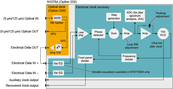
N1078A-S50 Block Diagram
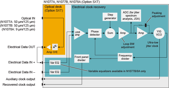
N1078A-SXT Block Diagram
Automatic Relock
If the clock recovery module loses lock, the trigger becomes asynchronous with the data and the instrument will not display a correctly triggered waveform. By default, when lock is lost, the instrument automatically tries to re-establish lock. Automatic relocking is most helpful when probing a device under test. You can turn off or on automatic relocking from the Clock Recovery setup dialog. Loss of lock, or false lock, conditions may be caused by unusual patterns with a large amount of consecutive 1's or 0's. If the module loses lock during any procedure or measurement, reestablish lock and then repeat the procedure or measurement. For example, if lock is lost while saving a pattern waveform to a file, the data stored in the file will be corrupt.
Locking on the Data Rate
When using the module, you must specify the symbol rate of the clock to be recovered and lock the module on the symbol rate. Under two conditions, the module may lock on a symbol rate other than the specified rate. In the first condition, lock can occur if the entered symbol rate is an integer multiple of the actual symbol rate of the signal. The second condition occurs because the acquisition range is broad (greater than ±5000 PPM). This makes it possible for the module to lock on a signal that is higher or lower than the selected value. For example, if you select a 2.48832 GBd symbol rate but the signal is actually 2.5 GBd, the module may still lock on the signal.
Loop Bandwidth and Jitter
When measuring jitter relative to the recovered clock, jitter that is present on both the data and the recovered clock can not be detected by the instrument. Jitter that is within the clock recovery module's loop bandwidth appears on the recovered clock. Jitter that is outside of the loop bandwidth does not appear on the recovered clock and can be detected on the data.
Specific jitter frequencies in the vicinity of the loop bandwidth may appear amplified or attenuated due to the scope timebase delay and clock recovery group delay. The electrical through-path does not have a delay line. Compensation can be made, by adding an electrical cable between the electrical output and the vertical channel. However, this may affect signal quality.
If the display shows a clock recovery lock lost status message, clock recovery cannot be established on the signal. Make sure that your signal is attached with a power level greater than the minimum (see the specifications) and that the symbol rate is set correctly to within the specified acquisition range.
Delay Matching
When using an N1078A, your test setup may require that additional delay be added. This can occur if the following items are true:
- An N1000A with option IPTB (Internal Precision Time Base) is used.
- Low frequency jitter in the order of a few 100 fs is present on the signal.
Added delay is not required if your test setup is using an 86107A precision timebase module or an 86108A/B precision waveform analyzer module. A delay-line assembly that adds the required amount of delay is provided in the N1027A-76A electrical clock recovery phase matching kit. This delay-line assembly attaches to the N1000A's rear panel. For instructions on installing the delay line and drawings of example test setups, download the N1076/7A user's guide from keysight.com.
An additional N1027A-77A optical clock recovery phase matching kit is also available that provides optical cables with specific amounts of delay for situations where clock-to-data delay is critical. The kit also provides general purpose multimode and single-mode optical cables, electrical cables, and microwave equalizers. For complete information on the kit and drawings of example test setups, download the N1076/7A user's guide from keysight.com.
Front-Panel Fiber-Optic Input
To avoid damaging the front-panel fiber-optic connector, use proper connection techniques.
Click here to learn about fiber-optic connector care. Use caution as fiber-optic end surfaces are easily damaged due to improper cleaning techniques and repairs can be expensive.
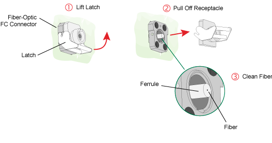
The N1077A's front-panel fiber-optic input adapter can be removed and cleaned as shown in the following picture. To remove the fiber-optic adapter:
- Lift the receptacle latch as shown in the following picture.
- Carefully pull off the receptacle without touching the ferrule or fiber end.
Options
| Option | Description |
|---|---|
| 264 | 125 Mbaud to 64 Gbaud |
| 253 | 53 Gbaud to 58 Gbaud |
| 232 | 125 Mbaud to 32 Gbaud |
| 225 | 25 Gbaud to 29 Gbaud |
| 216 | 125 Mbaud to 16 Gbaud |
| S50 | Internal single-mode splitter 50% to optical output, 9/125 μm |
| SXT | No splitter. User must supply. |
| Option | Description |
|---|---|
| EQ3 | Equalizer, 2.92 (m) to 2.92 (f), 3 dB. Reorder N1027A-EQ3. |
| EQ6 | Equalizer, 2.92 (m) to 2.92 (f), 6 dB. Reorder N1027A-EQ6. |
| EQ9 | Equalizer, 2.92 (m) to 2.92 (f), 9 dB. Reorder N1027A-EQ9. |
| CR1 | Electrical clock-recovery phase matching kit |
| 1CM | Rack-mount kit for a single N107X-series DCA-M |
| 1CN | Rack-mount kit for two N107X-series DCA-Ms (mounted side-by-side) |