Signal Processing and Jitter Measurement
FlexDCA can measure jitter and interference on the output waveforms of signal processing functions. However, if the input network contains a filter operation then signal processing jitter mode is used. Signal processing jitter requires amplitude measurements and is automatically turned on when needed. Example of filter operators include de-embedding, apply s2p, remove s2p, linear feedforward equalizer, and Gaussian filter.
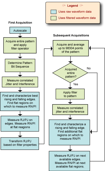
The following figure illustrates the steps used to perform jitter measurements on filtered waveforms. Notice that some of the steps use data from the raw input waveform and some of the steps use data from the filtered pattern waveform. Auto Scale is applied to the unfiltered data, so you may need to specify pattern parameters if they cannot be detected. The entire pattern is acquired continuously with new data averaged into the old data prior to being filtered. The filtered pattern is used to determine the symbol sequence.
For correlated jitter and interference measurements, DDJ is measured on all of the filtered waveform's edges, while ISI is measured on all of the symbol levels.
Figure. Acquisition Flowchart

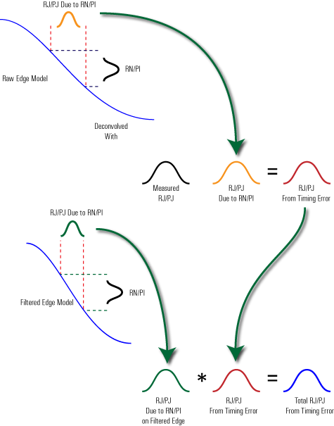
Uncorrelated jitter and noise measurements are aliased on equivalent-time sampling oscilloscopes such as the N1000A. As a result, the measurement can not be directly made on the filtered waveform data. RJ/PJ and RN/PI are measured on raw data and RJ/PJ is transformed to estimate RJ/PJ found on the filtered data. This is shown in the following picture. To perform the transform, the RJ/PJ is divided into jitter caused by timing and jitter caused by the RN/PI. Jitter due to RN/PI is calculated as it would appear on the edge in the filtered pattern. A final RJ/PJ number is determined by combining the jitter caused by timing and the jitter caused by RN/PI.
Since the algorithm uses RN/PI to determine the final RJ/PJ, adequately flat regions must be found on which to acquire the data. To avoid having the RJ/PJ contaminate the RN/PI measurement, the flat region should be wider than the jitter's width. The 7 symbol region acquired to characterize edges is used to find adequate flat regions. If a flat region cannot be found within the first two regions, narrower flat regions are used and the measurements are identified as questionable in the results panel.
Figure. Derivation of RJ/PJ

Edge locations for uncorrelated jitter measurements are estimated from the filtered data. This is because an edge's exact location is unknown since only the symbol timing of the filtered pattern is known. An area of 6 symbols around the estimated location is acquired and analyzed to find the exact location of the edge. The best edge is one that occures the farthest from any other edges. For example, a rising edge with 4 preceding zero's and 5 succeding one's is better than a rising edge with 6 preceding zero's and 3 succeding one's. If the waveform's edges can not be found, an error message is displayed.
RN/PI is not altered in this algorithm. If the filter has a large effect on the RN/PI, both RN/PI and RJ/PJ will be inaccurate. For example, this would occur if the input channel's bandwidth was 40 GHz, the filter's bandwidth was 5 GHz, and the noise was approximately equal across the entire spectrum.
Large RJ and RN measurements can occur even if the displayed eye looks like it is very clean with no noise or random jitter. Because eye diagram are created from the filtered and averaged pattern waveform, eye diagrams can appear clean regardless of the amount of jitter measured. Deterministic effects should still be visible in the eye.
If an RJ/PJ or RN/PI measurement fails and a message indicates that suitable edges or levels can not be found, confirm that the unfiltered waveform (even if the eye diagram is open) meets the following criteria. The offset between the raw and filtered waveforms should be less than 7 symbols. If the eye diagram is closed, at least one rising edge and one falling edge must both be clean and monotonic. There must be flat areas in the ones and zeros regions.
In the results panel, uncorrelated amplitude and jitter measurements can be labeled as questionable even though the RN/PI and RJ/PJ are reasonable measurements. This can occur when flat regions are not wide enough for accurate RN/PI measurements.