Gated Trigger
86100D gated triggering requires an 86100D to be running the 86100D's legacy Graphical User Interface (GUI). Gated triggering cannot be used from FlexDCA. To switch to the legacy GUI, click Apps > Legacy UI. To switch back to FlexDCA, either click Apps > FlexDCA or turn the instrument off and then on.

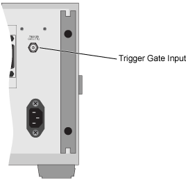
Trigger gating provides the capability to enable and disable the instrument's ability to respond to trigger inputs. You can use the gated trigger to examine selected segments of signals. For example, you may want to exclude specific time periods from being sampled. To use the gated trigger, you must connect a TTL control signal to the rear-panel BNC Trigger Gate (TTL) connector.
A short placed on the connector disables triggering. Gated triggering must also be enabled within the legacy GUI's Advanced Trigger Setup tab in the Trigger dialog. In the tab, select Gated Trigger.
Gated triggering is not available in Jitter mode or when the trigger source is Free Run.
| Gating Level | Characteristic Value |
|---|---|
| Disable | 0V to 0.6V |
| Enable | 3.5V to 5.0V |
| Maximum allowable range | 0.0V - 5.0V |
| Trigger Gate Signal VoltageLevel (TTL levels at rear-panel connector) |
Gated Trigger Selected (dialog box) |
State of Trigger Inputs |
|---|---|---|
| Level is not applicable | No | Enabled |
| Low | Yes | Disabled |
| High | Yes | Enabled |
| Signal is not connected | Yes/No | Enabled |
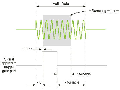
The trigger circuit will be enabled approximately 100 ns after a low to high gate signal transition. A high to low transition can require up to tdisable before data is no longer sampled, where

The maximum time displayed is equal to the time associated with the right hand side of the display graticule. The trigger period is the time between trigger edges.
The pulse width of the trigger gate control signal is recommended to be greater than 500 ns. The period of the trigger gate control signal is recommended to be greater than 1 μs.
To guarantee that valid data is sampled, the valid data must be available before the gate signal is confirmed high and at least tdisable after the gate signal is confirmed low. The following graphic illustrates this concept.
