This application is integrated into the VNA firmware as S9x460A/B.
|
Important Note When the first iTMSA measurement is created, an IFMUX Cal is performed, which takes a couple of minutes. When finished, Exit then restart the VNA App. If an IF board is replaced, this Cal should be performed again. To make this happen, delete c:\users\public\network analyzer\IFMUX.txt. When the next iTMSA measurement is created, the file will be recreated with new data. |
A seamless extension of existing VNA Balanced Measurement, but with True Mode stimulus.
True Mode Stimulus measurements are performed in a standard S-parameter channel.
2nd Source option
Opt S9x460A/B (software option only); must be enabled.
Direct Receiver Access configuration of the front-panel loops is NOT allowed. This bypasses the coupler making it no longer possible to perform return loss measurement of the DUT (needed to align the two sources). However, inserting amplifiers or other components into the standard source path configuration at the front-panel loops IS allowed.
Reversing the port couplers is NOT recommended due to the increased noise on the initial sweep for match correction. Good reflection measurements on all four ports is necessary to ensure adequate accuracy.
Does not support 1-port measurements.
Using true mode and measuring ADC inputs simultaneously may not result in accurate ADC measurements. In this case, adding two more ADC measurements to the display will result in accurate ADC measurements.
The measurement time will be long at the lower frequency below 10 MHz.
The measurement time will be long at the lower frequency below 10 MHz.
The following standard VNA features are NOT available with iTMSA measurements:
External Multiport Test Set Control (Option S9x551A/B)
Time Domain Pulse measurements in Wideband Pulse are NOT supported.
Frequency Offset Measurements (opt S9x080A/B)
A balanced device is designed to receive input simultaneously across two ports. Standard VNA Balanced measurements apply stimulus to one port at a time, measures the responses, and calculates the theoretical balanced responses. Learn more about balanced measurements.
True Mode Stimulus uses two VNA sources to apply either truly differential (180 degree out-of-phase) or truly common (in-phase) signals across the input of a balanced device. VNA receivers measure the single-ended response at the output of the device and calculate the balanced response.
When operating in non-linear regions, a device may respond differently to single-ended stimulus than to True Mode Stimulus. Thus, True Mode Stimulus capability allows you to understand when, and if, True Mode Stimulus is required.
For more detailed information on this measurement technique, see the following white papers (internet connection required):
New Methods & Non-Linear Measurements for Active Differential Devices
New Measurement Results and Models for Non-linear Differential Amplifier Characterization
The following is an overview of how iTMSA gathers and displays True Mode Stimulus data:
Initial sweep is performed to gather the initial phase deviation between the two sources at the reference plane.
Measurement The phase deviation between the two sources is set to the required value and the response is measured. For a differential sweep, the phase deviation of the two sources is set to 180° at the reference plane. For a common sweep, the phase deviation is set to 0° at the reference plan.
A forward direction measurement requires 2 sweeps for differential and 2 sweeps for common. A reverse direction measurement requires the same. Therefore, a complete measurement in both directions requires 8 sweeps. The iTMSA traces are updated when all of the necessary data is gathered in each direction.
iTMSA computes the raw S parameters with the following matrix:
Legend:
d1: differential stimulus in balanced port 1.
d2: differential stimulus in balanced port 2
c1: common stimulus in balanced port 1.
c2: common stimulus in balanced port 2.
A Standard (default) S-Parameter channel is used for iTMSA measurements.
How to create an iTMSA trace:
|
|
Using Hardkey/SoftTab/Softkey |
|
|
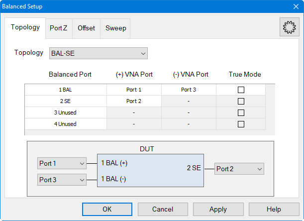
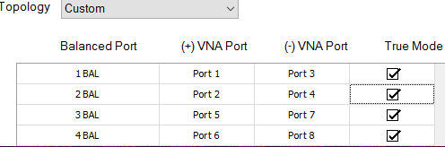
Balanced DUT Topology / Logical Port Mapping (with iTMSA Option S9x460A/B) dialog box |
|||||||||||||||||||||
Topology
The following topologies are available in True Mode Stimulus.
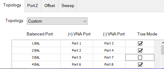
A balanced port can be any one of four physical port combinations: 1 - 3 1 - 4 2 - 3 2 - 4 For more than 4 ports systems in M980xA, iTMSA works with "ALL BAL" or "Custom" topologies.
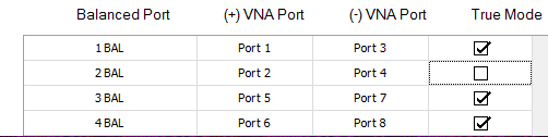
For multiport M980xA, there are more than two balanced ports. The true mode can be set by each balanced port. SCPI/COM below can be used to control this setting. SCPI: CALCulate<cnum>:FSIMulator:BALun:BPORt<pnum>:STIMulus:TRUe:STATe <bool> and CALCulate<cnum>:FSIMulator:BALun:BPORt<pnum>:STIMulus:TRUe:STATe?) COM: (BalancedStimulus.BalancedPortTrueState(bpnum) Port Z
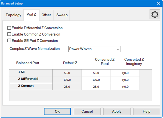
Provide an enable for both Common and Differential Conversion and SE Port Z Conversion. Complex Z Wave Normalization - Selects the wave normalization method. Power Waves - Waves are computed according to Kurokawa's power wave definition. Traveling Waves - Waves are computed according to a traveling wave definition. Balanced Port Shows all ports defined on the balanced topology page. Default Z Shows the default impedances that will be applied if the port Z conversions are not enabled. The SE Default Z always equals the System Zo defined for the VNA. The Differential and Common Default Z will display values calculated from the single-ended port impedances. Converted Z User may enter the real or imaginary component of the impedance.
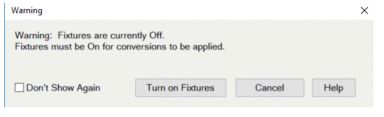
Warning Dialog The dialog is displayed if "Conversion" is enabled and "Apply Fixtures" is currently disabled.
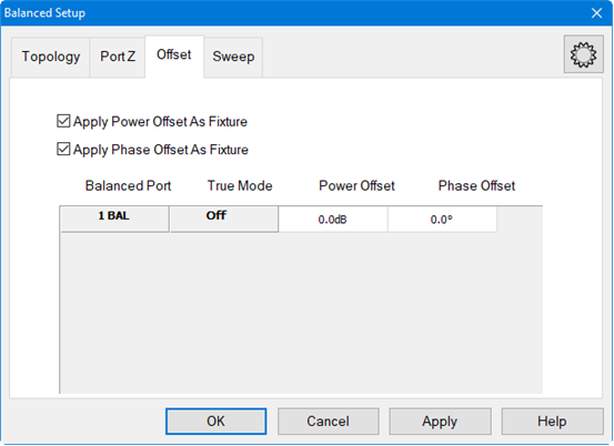
Offset
Balanced Port Set the phase or power offset for the balanced port. True Mode Shows whether True Mode is On or Off. Power Offset Specify power offset. Range is +/- 20 dB. This is in addition to the power level that is specified using the Power and Attenuators dialog. Offset Power is NOT reflected on the power dialog nor on the X-Axis during a power sweep. A power offset may only be applied to a True Mode port. Apply Power Offset as Fixture When unchecked, output calculations are performed and displayed as though there is no stimulus power offset. When checked, output calculations are performed and displayed using the power offset that is applied to the DUT. Use this setting to compensate for a component or fixture that may present a magnitude loss before the DUT. Phase Offset Specify offset for the balanced INPUT port. This is in addition to the standard offsets, which are 180° offset for the differential stimulus sweeps, and 0° for the common stimulus sweeps. A phase offset may only be applied to a True Mode port. Apply Phase Offset as Fixture When unchecked, output calculations are performed and displayed as though there is only the standard offset. Although additional Phase Offset is applied to the stimulus, it is ignored in the calculations of balanced differential and common mode output signals. When checked, output calculations are performed and displayed using the actual phase offset that is applied to the DUT. Use this setting to compensate for a component or fixture that may present a phase delay before the DUT. Sweep
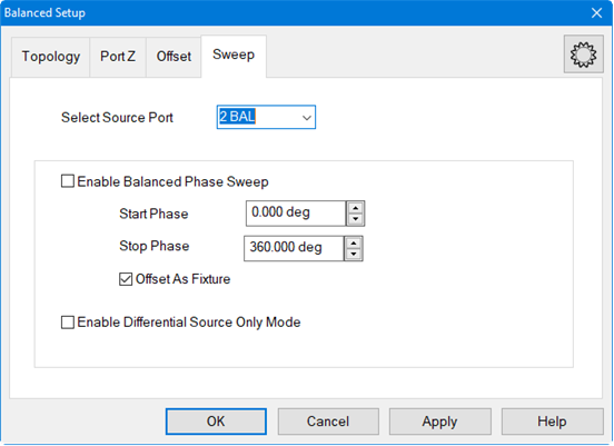
The phase of the selected active source port is swept relative to the phase of the other source port in the balanced pair. The active source port uses the logical port number. Phase Sweep is similar to phase offset, except that for each data point, the phase 'offset' is incremented. For example, with the topology that is selected in the above image: (Bal-Bal) Logical port 1 = VNA ports 1 and 3. For a phase sweep with 7 data points, from 0° to 180°, the phase difference between port 1 and port 3 increments 30° with each data point:
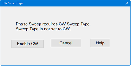
Enable Balanced Phase Sweep Check to enable phase sweep for the specified port. If enabled and the VNA sweep type is not CW, the following dialog is displayed to turn on CW Sweep Type.
Start / Stop Phase Enter phase values in degrees. Each sweep will start and stop at these settings. Offset as Fixture In the following image, the VNA phase sweep is shown as a phase shifter that is "virtually" located EITHER before the reference receiver (top) OR after the reference receiver (bottom) - NOT BOTH. This image is useful as a model ONLY.
Note: Beginning with firmware version A.14.00, the Enable Differential Source Only Mode feature has been changed to a SCPI-only feature. One use for Phase SweepDo the following to find the best operating point:
This measures the best possible case Sdd21 for the DUT. |
Set stimulus power levels using the standard VNA Power and Attenuators dialog.
To set power, press Power > Main > Power and Attenuators....
|
Power and Attenuation (with True Mode Stimulus) dialog box help |
|
When a True Mode Stimulus is selected in the Balanced DUT Topology dialog, the balanced ports are shown on the top rows of the dialog. The individual VNA port settings are displayed but can not be changed directly. Port Powers Coupled Check to couple all power settings for Balanced Port 1 and Balanced Port 2. Clear this box to make independent power settings for these logical ports. State Should be left in Auto for iTMSA measurements. Learn more about his setting. Port Power Set power for the balanced port. Power for VNA ports, shown below balanced ports, are set to 3 dB less, or half power. Power Offset is made in addition to this setting, and on only VNA port 3 and port 4. Offset Power is NOT reflected on this dialog nor on the X-Axis. Start and Stop Power Available when sweep type is set to power sweep. Auto Range Check to allow the VNA to select the optimum attenuation value to achieve the specified test port power. Clear to manually set the attenuation for each port. Type or select the attenuation value in the adjacent Attenuator Control box. When the attenuator setting of a logical port is changed, then the attenuators of the VNA ports associated with that logical port change to the same value. Leveling Mode Open Loop leveling is available only on ports 1 and 3. Learn more. Note: The range of leveled power (ALC range) for balanced ports is 3 dB higher than it is for each individual VNA port. For example, if a VNA source port with 0 dB attenuation will supply leveled power from -30dBm to +15dBm, then the balanced logical port has a range of -27dBm to +18dBm. Learn more about Leveled Power. |
Note: Uncalibrated True Mode Stimulus are NOT at all accurate.
Perform or recall a SMART Cal exactly like any other 3 or 4-port cal.
Press Cal > Main > Other Cals > Smart Cal....
All Cals are performed as single-ended.
Supports all Fixturing and Port Extension features.
Supports Guided Power Cal.
Supports Enhanced Response Cal and Source Power Cal.
Any pair of receivers can be viewed as a ratio using the following dialog.
To select these measurements, press Meas > Receivers.
|
Create / Change Receiver Measurements (with True Mode Stimulus) dialog box help |
|
Click Activate
For example, with a Bal-Bal topology, the above selections show a R3/R1 measurement. R (reference) receivers measure the stimulus to the DUT. An R3/ R1 trace shows the difference between the two sources that comprise logical port 1. With Log format, a power offset between the two sources is visible. With Phase format, a phase offset is visible. Source Port Specifies whether a Differential stimulus or Common mode stimulus is used for the measurement.
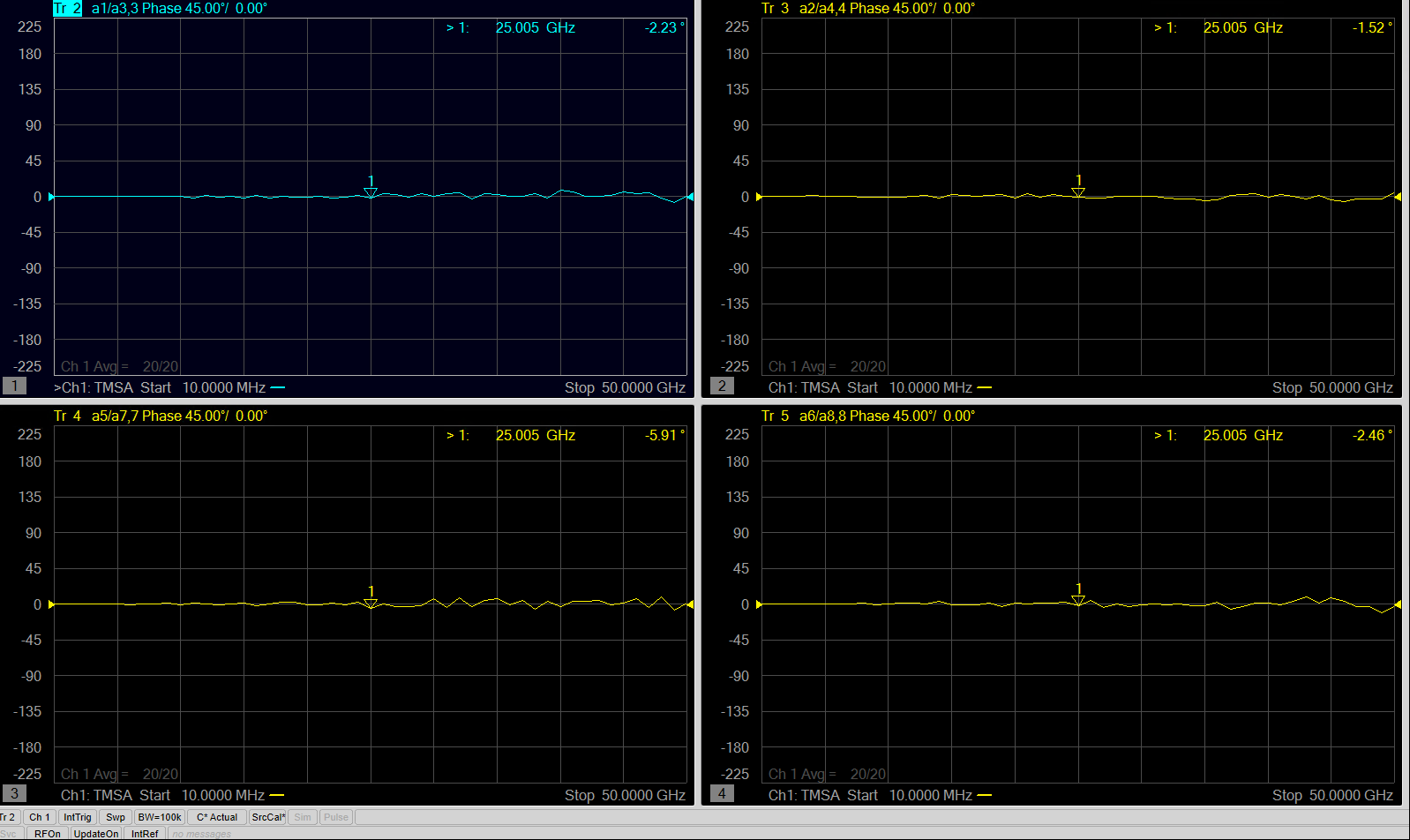
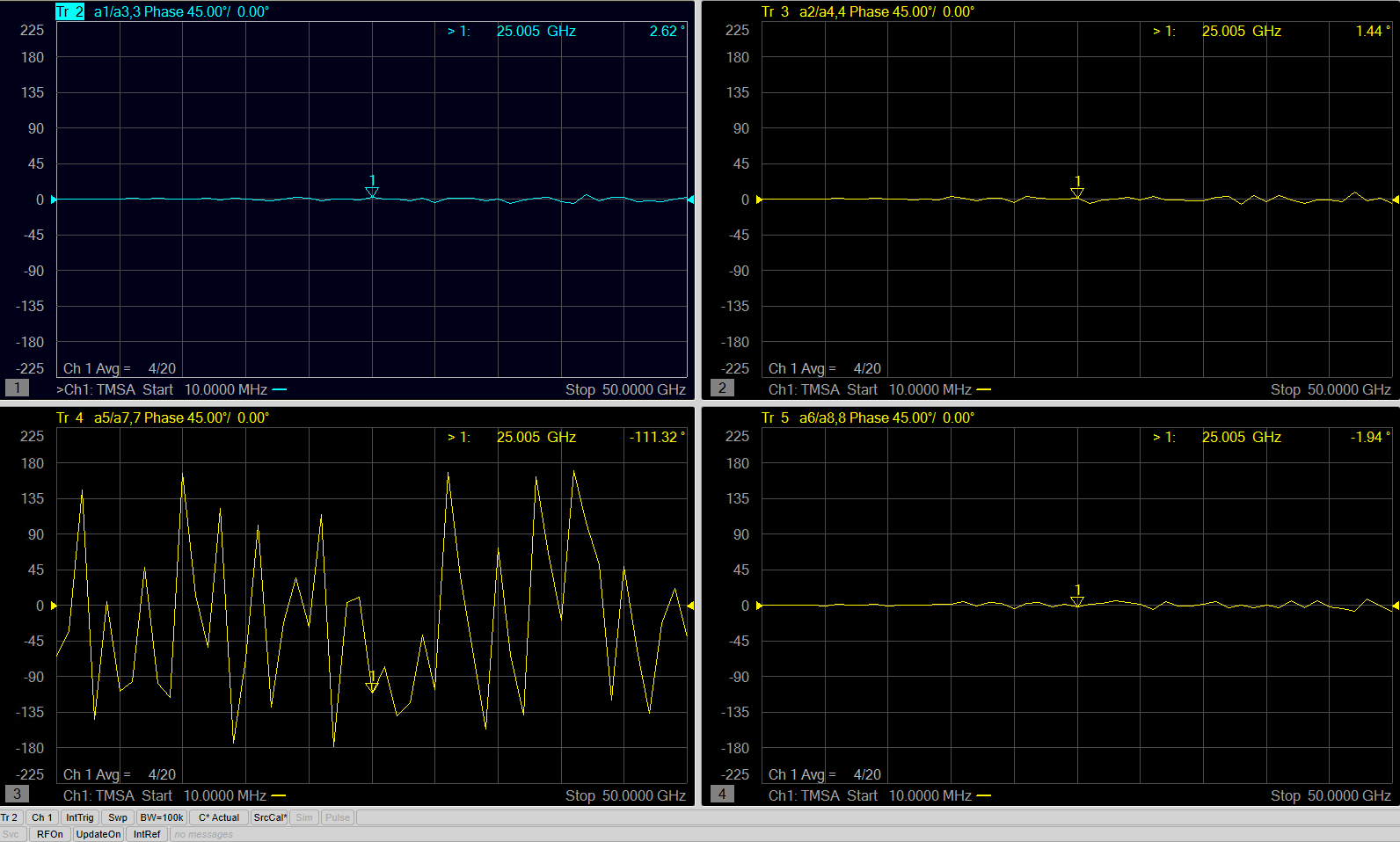
Measurement example for a 8 ports M980xA system: a) with true mode on all balanced ports
|
Equation Editor is used to calculate and display the Differential Input and Output power levels.
This procedure assumes a Bal-Bal topology which requires the following port assignments:
Balanced Port 1 = VNA ports 1 and 3
Balanced Port 2 = VNA ports 2 and 4
Preset the VNA
Perform a 4-port Guided Power Calibration if desired.
Then press Trace, select Trace Setup, then select Receivers.
Complete the dialog as follows, then click OK.
The above FIVE traces and the default (S11) trace should be visible on the VNA screen.
Click Tr1 (S11). This is the 'dummy' trace that will become an equation trace.
Then press Math > Analysis > Equation Editor....
In the Equation field, enter (Tr2-Tr4) / sqrt(2)
Press OK to close Equation Editor. The Tr1 trace is now showing Differential Output power.
For Differential Input power, activate Tr3 (C receiver).
In Equation Editor, enter (Tr5-Tr6) / sqrt(2). Press OK.
The Tr3 trace is now showing Differential Output power.
![]()
The traces used to calculate and display Differential Input and Output Power