TDEC

The TDEC (Transmitter and Dispersion Eye Closure) measurement for NRZ waveforms is a measurement of the quality of an optical transmitter with its optical link. TDEC is the optical power penalty of the measured optical transmitter compared to an ideal transmitter. It measures the increase of optical power required for the measured optical transmitter to achieve the same eye opening of the ideal optical transmitter. The lower the TDEC measurement, the higher the quality of the measured transmitter. TDEC is often used as a replacement for a Transmission Dispersion Penalty measurement. This measurement can be used with FlexDCA's Rapid Eye feature.
For compliance measurements on PAM4 or NRZ waveforms, use a Waveform Signal Processing TDECQ Equalizer operator.
For PAM4 waveforms, use the TDECQ measurement. Note that the TDECQ Equalizer operator can be applied to both NRZ and PAM4 waveforms.
Requires pattern lock. Ensure that Acquire Entire Pattern is selected. This note applies to FlexDCA and not FlexDCA running FlexRT.
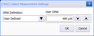
Because the TDEC measurement uses an OMA measurement to calculate TDEC, you are prompted to select how the OMA value is obtained. By default, the TDEC measurement automatically performs an Eye mode OMA at Crossing measurement to get an estimation of OMA. However, you can select User Defined for a more exact measurement as is explained in OMA Measurement Options below.
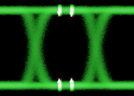
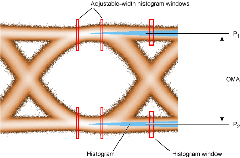
As shown in the following picture, two histogram windows are placed in time at the eye's crossing points, which occurs at adjacent one and adjacent zero levels. The resulting histograms give the mathematical mean of the one power level (P1) and mean of the zero power level (P0) in μW. OMA is the difference between the two means. Once the OMA in known, the TDEC measurement places histograms windows at 0.4 UI and 0.6 UI for both the one level and zero level as shown in the following picture. The width of these histogram windows is adjustable as explained in Configure Base Measurements Settings in this topic. These histograms are used in the calculation of TDEC.
This measurement applies to NRZ waveforms and not to PAM4 waveforms.
OMA Measurement Options
- User Defined OMA (Oscilloscope mode's OMA measurement)
- This is the recommended selection when measuring TDEC on a pattern locked signal. With this selection, you first must perform an Oscilloscope mode OMA measurement and enter the resulting value as the user-defined OMA for the TDEC measurement. OMA is the difference between the optical power of an NRZ one pulse and the optical power of an NRZ zero pulse. The Oscilloscope OMA measurement is designed to be made using an NRZ pattern that contains consecutive runs of ones and zeros as called out in many standards. This pattern allows the one and zero levels to settle out to minimize the effect of level transitions.
- OMA at Crossing (Eye mode's OMA at Crossing measurement)
- This is the default setting. The OMA value is automatically derived during the TDEC measurement using the OMA at Crossing measurement. Since a pattern of consecutive ones and zeros is not used during the OMA measurement (as is done when entering a user-defined OMA value), the resulting TDEC measurement can be too optimistic. This selection is best when the waveform is not the output of an equalizer.
- Waveform (intrinsic OMA measurement)
- Use this selection for measuring TDEC on a waveform that is the output of an equalizer. For example, with the new PON measurements standard. The OMA value is measured during the TDEC measurement on consecutive ones and zeros. Since a pattern of consecutive ones and zeros is used during the OMA measurement (as is done when entering a user-defined OMA value), the resulting TDEC measurement is more accurate when using equalization.
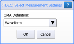
Starting with FlexDCA version A.06.90, using OMA at Crossing on a waveform that is the output of an equalizer results in the measurement being marked as questionable (?). In this case, select Waveform instead.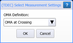
New OMA definition option starting with FlexDCA revision A0.6.90.
Configure Base Measurements Settings
The TDEC measurement is affected by the settings that are located in the TDEC/VECP tab of the Configure Measurements dialog (click Measure > Configure Base Measurements).
Reference Filter and Compliance Measurements
When making TDEC compliance measurements, a reference receiver 25 GBd filter (effective 12.6 GHz BW) is needed and is provided an N1092A/B/C/D/E Option 168 (25 GBd TDEC filter). To select the filter, open the optical channel setup dialog and in the Reference Filter field, select the TDEC (12.6 GHz) filter. This filter is not needed for non-compliant TDEC measurements.
To measure
- If you are performing a TDEC compliance measurement, click Setup > Modules > Channels to open the optical channel setup dialog. In the Reference Filter field, select TDEC (12.6 GHz) filter.
- Select Oscilloscope Mode and perform an OMA measurement according to the applicable standard. (recommended step)
- Select Eye/Mask Mode.
- Use the TDEC tab of the Configure Measurements dialog to customize the configuration of the measurement.
- Click the toolbar's Eye Meas tab.
- Click the TDEC button and enter the OMA measurement if performed in step 2 above.
SCPI Command
:MEASure:EYE:TDEC