Configure Measurements (Top-Base Definition tab)
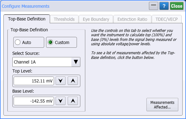
Use the Top-Base Definition tab of the Configure Measurements dialog to define the top and base levels which are used to locate the lower, middle, and upper threshold levels.

You can select either Auto or Custom Top-Base Definitions.
| Instrument Mode | ||
|---|---|---|
| Oscilloscope | Eye | TDR/TDT |
| Average | Eye Amplitude | Average |
| Duty Cycle | Eye Height | Fall Time |
| Fall Time | Eye Width | Rise Time |
| Rise Time | One Level | Δ Time |
| Frequency | Zero Level | Time at Edge |
| Preshoot | Fall Time | Time at Amplitude |
| Oversoot | Rise Time | |
| Period | Crossing Time | |
| + Pulse Width | Δ Time | |
| — Pulse Width | Crossing % | |
| Δ Time | Duty Cycle Distortion | |
| Time at Edge | Signal to Noise Ratio | |
| Time at Amplitude | Jitter | |
| RMS | Extinction Ratio | |
| Amplitude at Upper | OMA at Crossing | |
| Amplitude at Middle | VECP | |
| Amplitude at Lower | Bit Rate | |
| OMA | VECP | |
| Phase | ||
| Jitter | ||
Auto Top-Base Definitions
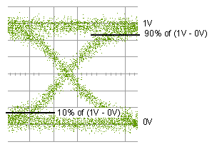
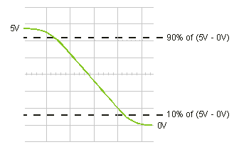
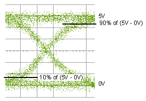
The Auto (default) setting computes the top (100%) and base (0%) levels, which are relative or proportional to the signal amplitude.
Top-Base definition values also affect Mask Test Alignment.


Custom Top-Base Definitions

The Custom setting allows you to enter absolute values for the top-base levels. Setting custom thresholds causes the measurement results table to display the text "user defined." The following table shows the amplitude units for the various waveform content windows.
| Name of Content Window Graphs | Amplitude Units | Example Source Waveform Selections |
|---|---|---|
| Oscilloscope, Eye, and TDR/TDT Modes | ||
| Window | Volts and Watts | Channel 2B Differential 1A Port 1+ (1A) |
| TDR/TDT T-Domain Parameters | ||
| Time-Ohms | Ohms | T11 Ohms |
| Time-Volts | Volts | TCC21 Volts |
| Time-% | Percent | T21 Percent |
| TDR/TDT S-Parameters and FFT Math Operator Waveforms | ||
| Freq-Mag | Decibels | FFT[2A] (F1) S21 Magnitude |
| Phase | Degrees | FFT[2A] (F2) S12 Phase |
| GrpDelay | Seconds | FFT[2A] (F3) SCD11 Delay |
The Custom option is not recommended when measuring eye diagrams.