Configure Measurements (Eye Boundary tab)
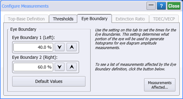
Use the Eye Boundary tab of the Configure Measurements dialog to set the time for the eye boundaries in Eye/Mask Mode. This setting determines what portion of the eye is used to generate histograms for eye diagram amplitude measurements.

Click Measurements Affected to view a list of measurements in which the measurement algorithm is affected by Eye Boundary definition changes:
- Eye Amplitude
- Crossing %
- Duty-Cycle Distortion
- Eye Height
- Signal to Noise Ratio
- One Level
- Zero Level
- Extinction Ratio
- VECP
Eye Boundary
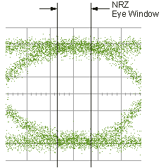
You can use the default values of 40% and 60% (central 20% of symbol period) for NRZ eye diagrams, or you can enter the values you want for the boundaries.
- Eye Boundary 1 (Left) allows you to set the time for the left side eye boundary.
- Eye Boundary 2 (Right) allows you to set the time for the right side eye boundary.

When you start a mask test, the instrument automatically aligns both the horizontal and vertical axis. There are two methods for aligning the vertical axis of a mask: Display and Eye Boundary. In Display mode, the instrument aligns the mask using the Vtop and Vbase values of the displayed waveform. This is the default mode for mask alignment. You can use Display mode for all mask tests.
In Eye Boundary mode, the instrument uses the one and zero levels of the waveform. The one and zero levels are defined as Eye Boundary 1 and Eye Boundary 2 in the Configure Measurement dialog. The Eye Boundary mode is typically used to align 10 GB Ethernet masks; it ensures that vertical alignment of the 10 GB Ethernet mask complies with industry standards. This alignment mode does not apply to fixed voltage masks.