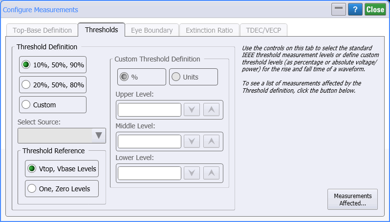
Configure Measurements (Thresholds tab)
Use the Thresholds tab of the Configure Measurements dialog to select the standard IEEE threshold measurement levels or define custom threshold levels (percentage or absolute voltage/power) for the rise and fall times of a waveform. If you want to assign specific amplitudes to the threshold levels, ensure the thresholds are within the limits of the top-base levels.

| Instrument Mode | ||
|---|---|---|
| Oscilloscope | Eye | TDR/TDT |
| Average | Duty Cycle Distortion | Average |
| Duty Cycle | Fall Time | Fall Time |
| Fall Time | Rise Time | Rise Time |
| Rise Time | Δ Time | |
| Frequency | Time at Edge | |
| Preshoot | Time at Amplitude | |
| Oversoot | ||
| Period | ||
| + Pulse Width | ||
| — Pulse Width | ||
| Δ Time | ||
| Time at Edge | ||
| Time at Amplitude | ||
| RMS | ||
| Amplitude at Upper | ||
| Amplitude at Middle | ||
| Amplitude at Lower | ||
| OMA | ||
| Phase | ||
| Jitter | ||
Threshold Definition
The standard IEEE threshold points are
- 10%, 50%, 90% for typical waveforms
- 20%, 50%, 80% for waveforms with excessive ringing or overshoot (often used for eye diagrams)
Threshold Reference (Eye/Mask Mode)
In Eye/Mask mode, the Threshold Reference selection is available and can be set relative to either the top (100%) and base (0%) levels or to the one and zero levels. Select the Top-Base Definition tab to change the definition of top and base. On the right side of the Thresholds tab dialog, a listing shows the measurements that are affected by the threshold settings.
Custom Threshold Definition
If you select the Custom threshold setting, click Select Source to select the source waveform (if more than one waveform is displayed), and % or Units to select the type of thresholds. In TDR/TDT mode, the available Source waveforms include channels (labeled Ports), T-domain parameters, and S-parameters. For parameters, the type of content window used is also indicated as shown in examples in the last column of the following table.
Selecting Units allows you to enter absolute amplitude levels, however, ensure that the thresholds are within the boundaries defined by the top-base levels. If the thresholds are outside the boundaries, the measurement results will report which threshold level is in question. You will then have to redefine the threshold levels and repeat the measurement.
Setting custom thresholds causes the measurement results table to display the text "user defined."
The following table shows the amplitude units for the various waveform content windows.
| Name of Content Window Graphs | Amplitude Units | Example Source Waveform Selections |
|---|---|---|
| Oscilloscope, Eye, and TDR/TDT Modes | ||
| Window | Volts and Watts | Channel 2B Differential 1A Port 1+ (1A) |
| TDR/TDT T-Domain Parameters | ||
| Time-Ohms | Ohms | T11 Ohms |
| Time-Volts | Volts | TCC21 Volts |
| Time-% | Percent | T21 Percent |
| TDR/TDT S-Parameters and FFT Math Operator Waveforms | ||
| Freq-Mag | Decibels | FFT[2A] (F1) S21 Magnitude |
| Phase | Degrees | FFT[2A] (F2) S12 Phase |
| GrpDelay | Seconds | FFT[2A] (F3) SCD11 Delay |
The Custom option is not recommended when measuring eye diagrams.
The 10% , 50% , 90% selection is often used for single valued waveforms. The percentage level is based on the measured or user defined values for Vtop and Vbase.
Selecting Volts as the units of measurement option will allow you to define absolute voltage values for the threshold levels. Top-base levels are independent of the measurement when Volts mode is selected for the threshold level. Therefore, the top-base levels are not used and do not need to be set. The instrument will only use the values defined for the threshold levels in the period measurement calculation. If you are measuring an optical channel, please note that the measurement result be displayed as Watts .
Rise time and fall time measurements do not require you to enter a value for the middle level threshold.
Top-base levels are not used in the fall time calculation when threshold levels are set to absolute voltages. Therefore, the top-base levels do not need to be set in this mode.