Configure Measurements (TDEC/VECP tab)
 Use the TDEC/VECP tab of the Configure Measurements dialog to customize the configuration of Eye/Mask Mode's TDEC (Transmitter and Dispersion Eye Closure) measurement and VECP (Vertical Eye Closure Penalty) measurement.
The NRZ TDEC measurement settings in this dialog tab are the same settings found in the TDECQ Reference Equalizer Setup dialog's TDEC Measurement tab. Change a setting in one of these dialogs and the setting is changed in both places.
TDEC/VECP Histogram Width
The histogram windows used in the TDEC and VECP measurements are set to a default width of 0.04 UI. This setting is applied when FlexDCA is not in pattern lock. It adjusts the histogram window so that additional data can be acquired to decrease the measurement time. The window's width can be set from 0.01 UI to 0.20 UI. The default setting is 0.04 UI. The default value is the same value used in 100GBASE-SR4.
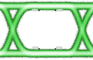
| Minimum Width (0.01 UI) | Maximum Width (0.20 UI) |
|---|---|
| TDEC Measurement (four histogram windows) | |
|
|
| VECP Measurement (two histogram windows) | |
|
|
Histogram Position
The position of the left and right histograms can be positioned on the waveform. The position of the left histogram can be set from 0.25 UI to 0.50 UI. The position of the right histogram can be set from 0.50 UI to 0.75 UI.
Minimum Zero Level and Minimum One Level Runs
Enter the minimum number of consecutive zero or one UIs that must be present in the waveform. If the runs are shorter, the measurement is marked a questionable (a "?" character annotates the measurement's results).
Level Measurement Length
Enters the level measurement length in UI for measuring TDEC. The length can range from 2 UI to 1,024 UI depending on the Minimum Zero Level Run and Minimum One Level Run settings. The level measurement length must fit within the specified minimum allowed level runs.
TDEC Target BER
The optical power penalty of the measured optical transmitter is based on the amount of noise that would need to be added to obtain a target BER. The default setting is 5 x 10⁻⁵ BER, which is called out for 100GBASE-SR4 which uses FEC. The range of values can be from 1 x 10⁻¹² to 1 x 10⁻¹. Target BER is applied to TDEC measurements only and not to VECP measurements.
TDEC Modal Noise Factor
Modal Noise Factor is a property of the fiber-optic link that is connected to the output of the optical transmitter DUT. The default setting is 1.75 x 10⁻². The range of values can be from 0 to 5 x 10⁻¹. Mode Noise Factor is applied to TDEC measurements only and not to VECP measurements.
TDEC Mode Partition Noise Factor
Mode Partition Noise Factor is a property of the fiber-optic link that is connected to the output of the optical transmitter DUT. The default setting is 4.0 x 10⁻². The range of values can be from 0 to 5 x 10⁻¹. Mode Partition Noise Factor is applied to TDEC measurements only and not to VECP measurements.
TDEC One Level Noise Gain
Sets the TDEC measurement's One Level Noise Gain which affects TDEC and VECP measurements. The default value is 1.000 and the range is 1.000 to 12.000.
Presets
Presets allow you to save your dialog settings to a setup file. To save your settings, click the  button. Select a preset in the drop-down list to instantly configure your TDEC setting to your specification. You can save as many presets as you need. The Preset list shows all of the factory provided presets as well as any that you have created.
TDEC Measurement Presets
- 400G CWDM8 MSA 10km Optical Interface
- IEEE 802.3bm (100 GbEn)
- ITU 50G PON
- Stressed Eye Closure (SEC)
- T11 FC-PI-6P (32xFibre Channel)
If you scroll to the end of the list and click the <Edit List> entry, the Edit TDEC Presets List dialog opens which allows you to reorder, delete, or rename items in the list. In the list, the names of factory provided presets includes the text (factory) which indicates that the entry cannot be edited.