N1040A 20/33/44/60 GHz Electrical Module
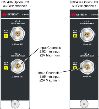
The N1040A is a dual-channel electrical mini module. The module occupies one of the four module slots on the DCA-X mainframe.

An N1040A with a serial number ≥ US62100101 requires FlexDCA firmware version A.06.90 or later.
For N1040A modules with a serial number < US62100101, the minimum required firmware version is A.06.55 (FlexDCA) for both the N1000A and 86100D.
The maximum input voltage is ±2V.
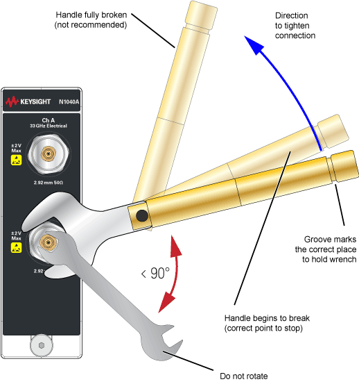
Avoid expensive damage! Refer to Connecting a Connector Saver to a Channel to learn how to safely connect adapters and cables to the module's electrical channels.
| Model/Option Number | Description | Ships Standard with Module |
|---|---|---|
| N1040A | Dual Electrical channel module | ● |
| N1040A-033 | 20/33 GHz bandwidth, 2.92 mm inputs | ● |
| N1040A-060 | 20/33/40/60 GHz bandwidth, 1.85 mm inputs | |
| N1030A-IRC | Impulse response correction to provide ideal channel response. | ● |
| N1040A-C0C | Certificate of calibration | ● |
| N1040A-UK6 | Commercial calibration certificate with test data |
| Description | Quantity |
|---|---|
| Getting Started Card. | 1 |
| DCA-X Filler panel | 1 |
| ESD Warning Sticker Sheet | 1 |
| ESD Warning Pamphlet | 1 |
- 1. This table shows a partial list. Refer to the shipping list that is shipped with the product for a more accurate lising.
Option IRC
Option IRC provides optical channel System Impulse Response Correction (SIRC) measurement and data files. These files provide an ideal channel response. SIRC data can be applied in the System Impulse Response Correction dialog. The SIRC correction data feature is a digital filter that is used to:
- Improve the response of module reference filters to more closely match an ideal receiver.
- Enable non-standard reference receiver rates or bandwidths.
- Increase the bandwidth of the channel by up to 50%.
- Ensures that an eye diagram will look identical between different modules.
SIRC correction data is unique to a specific module (serial number). Option IRC ships standard with every module and does not need to be purchased.
| Module/Option | Channel | Range1 Min SIRC Freq. |
Range1 Max SIRC Freq. |
|---|---|---|---|
| N1040A Option 033 | All | 10 GHz | 38 GHz |
| N1040A Option 060 | All | 10 GHz | 70 GHz |
Only available with option IRC and compliance not guaranteed.
Connecting a Connector Saver to a Channel
The following picture shows the proper technique when connecting the supplied connector saver to a channel. The connectors on N1040A-033 modules are 2.92 mm. The connectors on N1040A-060 modules are 1.85 mm. To protect the input connectors, it is recommended that you always use the connector saver, which comes already connected to the channel inputs. Torque the connection to 8 in-lb for both 1.85 mm and 2.92 mm connectors.

Connecting a Cable to a Connector Saver
Torque the connection to 8 in-lb.
