System Impulse Response Correction Setup
Use the System Impulse Response Correction Setup dialog to apply and configure a module's System Impulse Response Correction (SIRC) data.
To open this dialog, click Setup > Modules > Channels X to open the channel setup dialog. In the Bandwidth field, click the Configure button.
The SIRC correction data is a digital filter that is used to improve the response of the input channel's reference filters to more closely match an ideal receiver. SIRC data is unique to a specific DCA-M or N1000A plug-in module's model and serial number. In most cases, SIRC is provided as Option IRC. If the module includes option IRC, the following additional capability is added:
- Enable non-standard reference receiver rates or bandwidths.
- Increase the bandwidth of the channel by up to 50%.
- Ensures that an eye diagram will look identical between different modules.
SIRC calibration data is stored inside DCA-M and N1000-series plug-in module memory. At the top of the dialog, a message shows if the data is currently loaded  or missing
  .
.
Pattern lock must be turned on before SIRC data can be applied.
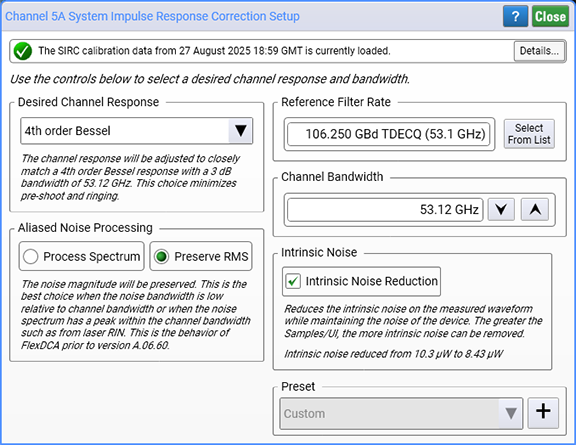
At the top of the dialog, you can select and modify the SIRC filter. The field names and selections may change depending on an electrical or optical module. Use the Preset field which is located at the bottom of the dialog to save your selections and to load custom and standard presets. The Preset field includes standard presets for N1060A and N1046A modules. Any change to the bandwidth setting is also shown in the channel setup dialog.
Electrical SIRC Presets
- 33 GHz Bessel (Ethernet)
- 40 GHz Bessel (OIF-CEI)
- 40 GHz Butterworth (802.3ck)
Intrinsic Noise
The Intrinsic Noise Reduction setting reduces intrinsic noise and jitter that is present on the waveform. Any noise that is contributed by the device under test will not be reduced and will be included included on the waveform and in any measurements. Increasing the Samples/UI setting (in the Acquisition Setup dialog), increases the amount of intrinsic noise that can be removed. The Intrinsic Noise Reduction setting is on by default.
Intrinsic Noise Reduction requires Pattern lock and Acquire Entire Pattern settings selected, with SIRC applied.
Because the entire pattern must be acquired, there can be a delay in time before waveform data is displayed.
When this setting is turned on, if you are applying a TDECQ Equalizer to the waveform it is recommended that you turn the operator's TDECQ Operator (Advanced) setting off.
Unlike the TDECQ equalizer's Low-SNR Measurement Mode setting, a Precision Timebase (PTB) can be turned on when using Intrinsic Noise Reduction.
Noise Processing and SIRC
FlexDCA's SIRC feature allows the channel response to be corrected with a digital filter. A channel that allows SIRC is one that has been measured or characterized in both magnitude and phase. The following two figures show the configuration dialogs for SIRC for both optical and electrical channels. The dialog's options (fields) are described in this section.
Desired Channel Response Option
The Desired Channel Response options refer to the desired channel frequency response after correction. The following sections describe the choices available, and the following figure compares the spectral magnitude responses.
4th order Bessel
This is the response of typical optical reference receiver. For NRZ standards the cutoff frequency is usually set to 75% of the symbol rate while for PAM4 TDECQ measurements the frequency is set to 50% of the symbol rate. The 4th order Bessel response is a causal filter that has minimal ringing and inter-symbol interference.
Sin(x)/x (Brick Wall)
The sin(x)/x or brick wall response is the typical response of a real-time scope. It fully captures the behavior of a band-limited signal provided that the test signal’s bandwidth is less than the specified response bandwidth. If the spectrum of the signal is not fully contained within the selected response bandwidth, this response will introduce ringing and non-causal artifacts. This is typically used within FlexDCA to correlate measurements with real-time oscilloscopes.
Butterworth
The 1st, 2nd, 3rd, and 4th order Butterworth filter options are useful when the scope response is required to match a reference receiver response with the same shape. For example, IEEE 802.3ck specifies a 4th order Butterworth response.
Flat
The flat correction does perfect magnitude and phase correction out to the desired bandwidth, just like the Brick Wall response. However, instead of rolling off at that frequency, the correction is gradually reduced to follow the response of the channel. This generally will maximize the available bandwidth while minimizing the introduction of non-causal effects for signals that are not fully band-limited.
| Channel Legend |
|---|
| Raw Channel |
| 40 GHz 4th Bessel |
| 40 GHz Sinc |
| 40 GHz 4th Butterworth |
| 40 GHz Flat |
Reference Filter Rate & Channel Bandwidth
The Reference Filter Rate setting is only available for optical channels and only when the channel response is set to Bessel. This allows you to select a symbol rate instead of a bandwidth value. The channel bandwidth is always available.
However, note that the relationship between symbol rate and bandwidth is not one-to-one. There are multiple rates that map to the same bandwidth and multiple bandwidth that map to the same rate. For example, the symbol rate 26.5625 GBd has four different bandwidths that may be associate with it:
- 19.34 GHz is the bandwidth for NRZ mask measurements,
- 12.6 GHz is the bandwidth for NRZ TDEC measurements,
- 13.28 GHz is the bandwidth for PAM4 TDECQ measurements in single-mode fiber, and
- 11.2 GHz is the bandwidth for PAM4 TDECQ measurements in multi-mode fiber
Going the other direction, there are multiple symbol rates that map to the same bandwidth. For example, 19.34 GHz is the correct 3 dB bandwidth for both:
- 25.78125 GBd (NRZ), and
- 26.5625 GBd (NRZ)
This lack of correspondence can make remote programming difficult. However, problems will be minimized if the following rules are followed:
- For NRZ mask/eye testing, set the symbol rate using the
:CHAN:SIRC:FRATeSCPI command. - For TDECQ and TDEC testing, set the bandwidth using the
:CHAN:SIRC:FBANndwidthSCPI command.
FlexDCA's SCPI Recorder properly reports the preferred syntax based on the filter selected.
Aliased Noise Processing
The Aliased Noise Processing field has two settings: Preserve RMS and Process Spectrum.
Preserve RMS
Preserve RMS will preserve the magnitude of the noise. This is the best choice when the spectrum of the noise has a significant peak within the bandwidth of the channel or when an uncorrelated but deterministic signal is known to be present on the signal. An example of this is laser RIN (Relative Intensity Noise) which typically has a peak below the modulation bandwidth. The following figure shows an example of RIN measured for various conditions of the laser. The measurements are from the Keysight RIN measurement system.
Another instance where Preserve RMS is appropriate is when low frequency interference is present on the signal due to cross talk or intentional closure in stressed eye testing.
Process Spectrum
The other aliased noise processing option is Process Spectrum. This option assumes that the aliased (uncorrelated to the trigger) signal components have the same power spectrum as the measurement channel. In this case, if SIRC is reducing bandwidth the magnitude of the noise on the output signal will be correspondingly reduced, whereas if SIRC is increasing bandwidth the magnitude of the noise will be increased.
In many cases the difference between Preserve RMS and Process Spectrum will be slight. For example, optical modules generally provide reference filter selections that are compliant with a tolerance window. Even though they are compliant, there still can be phase and magnitude variations from an ideal 4th order Bessel shape. SIRC can dramatically improve channel-to-channel correlation of measurements like mask margin even while making only slight modifications to the power spectrum of the measured signal. In this common situation, it will make little difference which noise processing option is selected.
The situation where noise needs to be carefully considered is when SIRC is used to significantly increase or decrease the bandwidth of the module.