N1030A Optical/Electrical Module
The N1030A is a single-channel optical mini module. Option EC1 adds an electrical channel that has a 1 mm female RF input connector. The module occupies one of the four module slots on the DCA-X mainframe.
An N1030A with a serial number ≥ US62100101 requires FlexDCA firmware version A.06.90 or later.
For N1030A modules with a serial number < US62100101, the minimum required firmware version is A.06.55 (FlexDCA) for both the N1000A and 86100D.
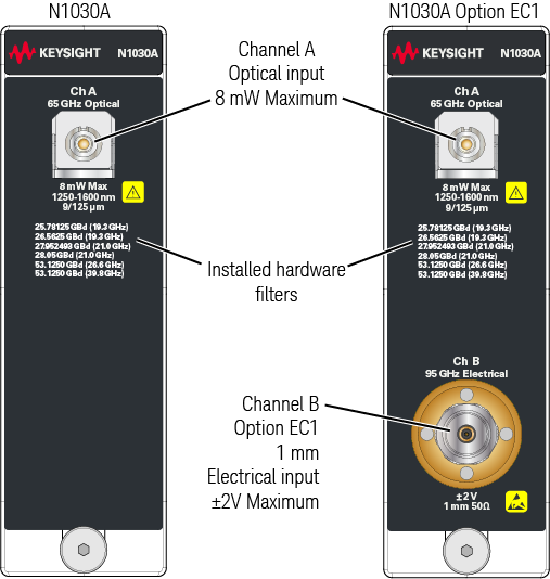
On optical channels, the maximum optical input power is 8 mW.
On the N1030A-EC1 electrical channel, the maximum input voltage is ±2V.
Avoid damaging N1030A-EC1 modules! Refer to N1030A Accessory Kit to learn how to safely connect adapters and cables to the module's 1 mm electrical channel.
| Model/Option Number | Description | Ships Standard with Module |
|---|---|---|
| N1030A | Single optical channel module | ● |
| N1030A-EC1 | Adds 95 GHz electrical channel | |
| N1030A-65U | 65 GHz optical bandwidth | ● |
| N1030A-560 | 53 GBd to 56 GBd PAM4 hardware filters | ● |
| N1030A-280 | 25 GBd to 28 GBd NRZ hardware filters | |
| N1030A-IRC | Impulse response correction to provide ideal channel response. | ● |
| Module | Option | No. of optical channels |
Wavelength range (nm) | Unfiltered optical bandwidth (GHz) |
Fiber input (μm) | No. of electrical channels |
Highest electrical bandwidth (GHz) |
|---|---|---|---|---|---|---|---|
| N1030A | — | 1 | 1250 - 1600 | 65 | 9/125 | 0 | — |
| EC1 | 1 | 1250 - 1600 | 65 | 9/125 | 1 | 95 |
| Description | Quantity |
|---|---|
| Getting Started Card | 1 |
| N1030A-ECR Accessory Kit. Refer to N1030A Accessory Kit in this topic. | 1 |
| DCA-X Filler panel | 1 |
| ESD Warning Sticker Sheet | 1 |
| ESD Warning Pamphlet | 1 |
- 1. This table shows a partial list. Refer to the shipping list that is shipped with the product for a more accurate lising.
| Filter Rates | N1030A/B Options (with Opton IRC) | ||
|---|---|---|---|
| 280 | 430 | 560 | |
| 25.78125 Gbd (19.3 GHz) | ● | ● | |
| 26.5625 Gbd (19.3 GHz) | ● | ● | |
| 27.952493 Gbd (21.0 GHz) | ● | ● | |
| 28.053 Gbd (21.0 GHz) | ● | ● | |
| 53.1250 Gbd (26.6 GHz) | ● | ● | |
| 53.1250 Gbd (39.8 GHz) | ● | ● | |
Option IRC
Option IRC provides optical channel System Impulse Response Correction (SIRC) measurement and data files. These files provide an ideal channel response. SIRC data can be applied in the System Impulse Response Correction dialog box. If an module is installed in an 86100D, the 86100D must be in Standard or Compatibility configuration. The SIRC correction data feature is a digital filter that is used to:
- Improve the response of module reference filters to more closely match an ideal receiver.
- Enable non-standard reference receiver rates or bandwidths.
- Increase the bandwidth of the channel by up to 50%.
- Ensures that an eye diagram will look identical between different modules.
SIRC correction data is unique to a specific module (serial number). Option IRC ships standard with every module and does not need to be purchased.
| Module/Option | Channel | Range1 Min SIRC Freq. |
Range1 Max SIRC Freq. |
|---|---|---|---|
| N1030A Option 560 | All Optical | 21.5 GBd (16.13 GHz) | 80 GBd (60 GHz) |
| N1030A Options 280 and 560 | All Optical | 15.6 GBd (11.7 GHz) | 80 GBd (60 GHz) |
| N1030A Option EC1 | Electrical | 20 GHz | 127 GHz |
Only available with option IRC and compliance not guaranteed.
N1030A Accessory Kit
The N1030A accessory kit includes the required torque wrenches, open-end wrenches, and adapters to make connections to the N1030A’s front-panel 1 mm electrical RF connector. To prevent expensive repairs and repair downtime, take a few minutes to study the information in the following pages.
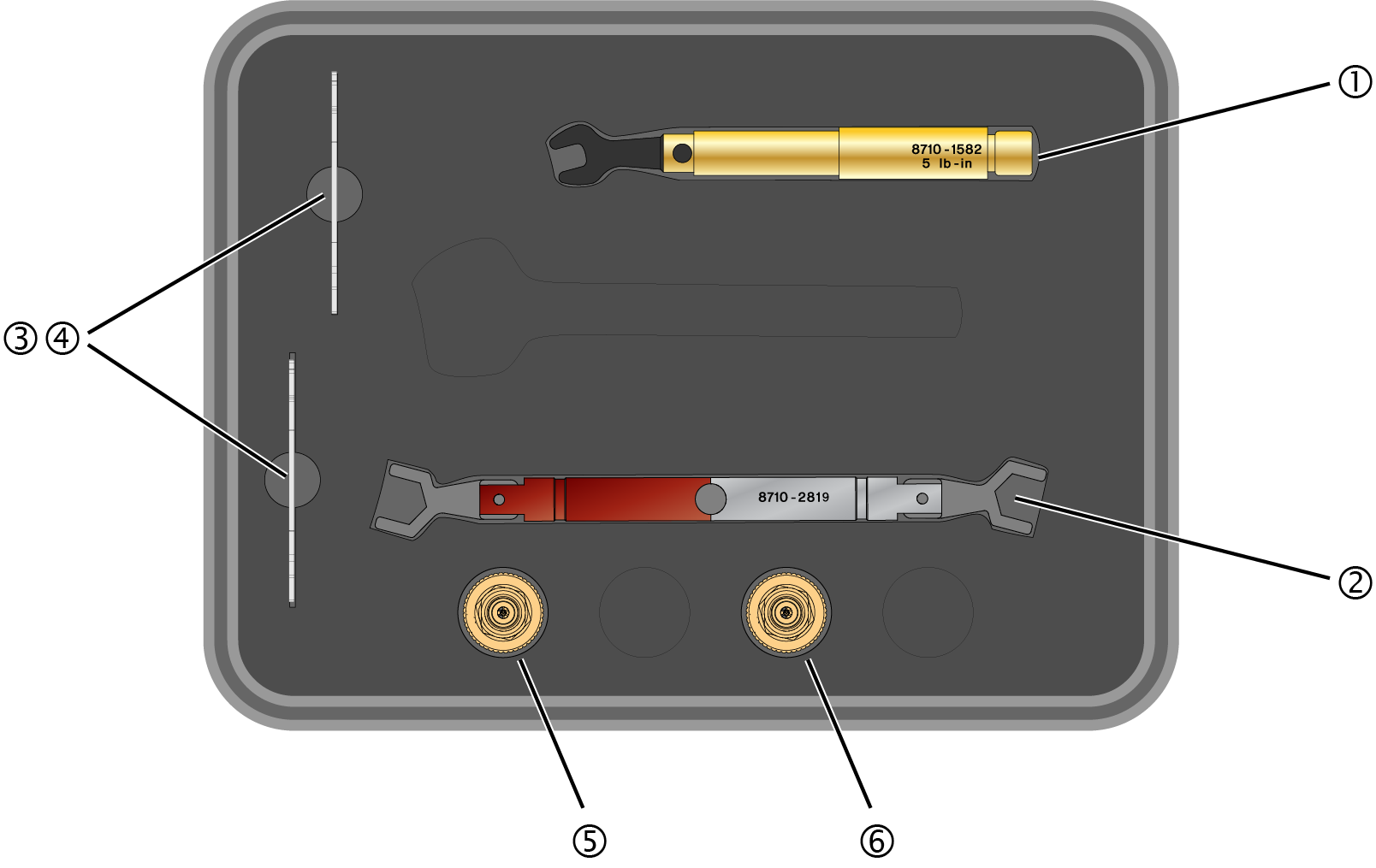
| Item | Description | Qty | Part Number |
|---|---|---|---|
| 1 | Torque wrench, 5/16-in open end, 5 lb-in (0.57 Nm) | 1 | 8710-1582 |
| 2 | Dual Torque wrench, 14 mm open end, 4 lb-in (0.45 Nm) and 10 lb-in (1.13 Nm) |
1 | 8710-2819 |
| 3 | Open end wrench, 8 mm | 1 | N1060-20009 |
| 4 | Open end wrench, 7 mm | 1 | 8710-1761 |
| 5 | Channel Input adapter, 1 mm (f) to 1.85 mm (f) | 1 | Y1901B (5067-1392) |
| 6 | Channel Input adapter, 1 mm (f) to 2.92 mm (f) | 1 | Y1903B (5067-1393) |
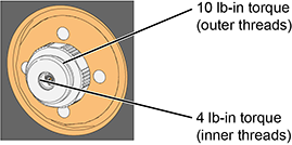
Channel Input Connectors
On several DCA-X modules and DCA-M modules, a front-panel 1 mm Channel Input connector is used as shown in this picture. These 1 mm connectors have both outer in inner threads that require different torque specifications. Always use the correct torque specification as noted when making connection to the Channel Input. Damage to the Channel Input connector results in an expensive repair and extended down time while the module is being repaired.
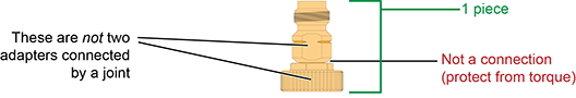
Channel Input Y1901/3B Adapters
The following picture show the two types of ruggedized 1mm adapters, which are supplied in the N1030A and N1060A accessory kits:
- 1 mm to 1.85 mm Y1901B adapter
- 1 mm to 2.92 mm Y1903B adapter
These adapters are designed to be installed on the front-panel channel inputs. It is recommended that you always use them. Due to the physical requirements needed to obtain high performance, the geometry of these, as well as all, 1 mm connectors, demands special care to avoid expensive damage as explained in this document.
Making RF Connections
- Work at a static-safe workstation.
- Visually inspect the connectors. If necessary, clean the connectors. Carefully align the connectors. The male connector center pin must slip concentrically into the contact fingers of the female connector.
- Push the connectors straight together.
- Tighten lightly using only your fingers as, at this point, all you want is a connection in which the outer conductors make gentle contact at all points on both mating surfaces. Very light finger pressure (no more than 2 pound-inches of torque) is enough.
Do not twist one connector into the other (like inserting a light bulb). This happens if you turn the device body rather than the connector nut. Major damage to the center conductor can occur if the device body is twisted.
- Use a torque wrench to make the final connection. This guarantees perfectly tight, consistent connections that prevents connector damage. Refer to Applying Torque for the proper handling of the wrenches and to view the correct connector “flats” on which to position the wrenches.
The maximum torque setting is 4 in-lb (0.45 Nm) for 1.0 mm connectors.
Rotate only the connector nut when you make the connection. Do not rotate the cable or adapter.
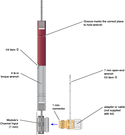
Hold the torque wrench lightly at the groove located at the end of the handle.
Apply force perpendicular to the wrench handle. This applies torque to the connection through the wrench. Do not hold the wrench so tightly that you push the handle straight down along its length rather than pivoting it, otherwise you apply an unlimited amount of torque.
Tighten the connection just to the torque wrench "break" point as shown in Wrenches Positioned on Correct Flats. Do not tighten the connection further.
Applying Torque
For the 1 mm Channel Input connector, use the dual torque wrench shown in the Wrenches on Channel Input.
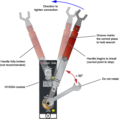
The silver end of the dual torque wrench is 4 lb-in. The red end of the torque wrench is 10 lb-in.
Selecting and Positioning the Wrenches
The following figures show the proper “flats” on which to place the wrenches for several possible connections.
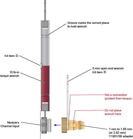
Y1901/3B Adapter to Channel Input
This figure show the correct placement of the 10 lb-in dual torque wrench (the red end) and the 8 mm open end wrench. On the Y1901/3B adapter, connect the 8 mm wrench on the flats that are adjacent to the knurled ring as shown in this figure.
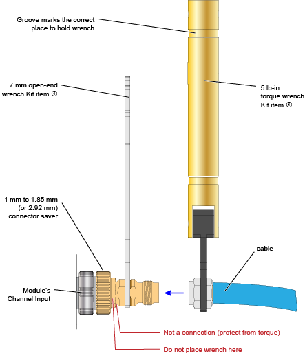
Cable or Adapter to Y1901/3B Adapter
This figure show the correct placement of the 5 lb-in torque wrench and the 7 mm open end wrench for connecting a cable, adapter, or other item to the Y1901/3B adapter.
Adapter to Channel Input (without Y1901/3B)
It is recommended that you always connect an Y1901/3B adapter to the 1mm channel input. However, if you want to connect an adapter or cable directly to a channel input connector, use the 4 lb-in end of the dual torque wrench (silver end of the dual torque wrench). Do not use the red end of the dual torque wrench which is only used when connecting the stronger outside channel-input connector threads to the Y1901/3B connector.
Never apply in excess of 4 lb-in of torque to the 1mm channel input’s inner threads. Confirm also that your adapter or channel connector can withstand 4 lb-in.