N1045A/B Electrical Remote Sampling Head Module

The N1045A/B electrical sampling head modules provides 2 or 4 measurement channels with either 1.85 male or female RF input connectors. The module occupies only one of the four module slots on the 86100D. Because the N1045A/B remote heads contain the sampling electronics, the distance between the sampling and the probe stations or the device under test (DUT) can be made with very short or without cabling. By using a reduced amount of cabling, measurement degradation is minimized. The result is more accurate high-speed electrical measurements. This module scales the input signal, sets the bandwidth of the system, and allows the offset to be adjusted so the signal can be viewed. The output of the module is an analog signal that is applied to the ADCs on the acquisition boards inside the mainframe.
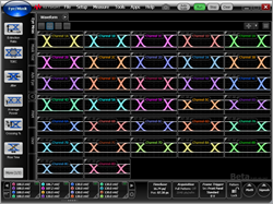
When four N1092D DCA-M optical sampling oscilloscopes are connected to an 86100D that has four N1045A/B-04X mini modules, you have a total of 16 optical channels and 16 electrical channels. All of the 32 channels can be displayed at the same time.
An N1045B with a serial number ≥ MY62100101 requires FlexDCA firmware version A.06.90 or later.
For N1045B modules with a serial number < MY62100101, the minimum required FlexDCA firmware version is A.06.00 (FlexDCA).
For N1045A modules, the minimum required FlexDCA firmware version is A.02.00 (FlexDCA).
The maximum input voltage is ±2V.
This maximum torque setting is 5 in-lb (0.57 Nm) for 1.85 mm connectors.
Before removing the module from the DCA-X, coil the remote head cables. This reduces the possibility of dropping one or both remote heads.
Option IRC
Option IRC provides optical channel System Impulse Response Correction (SIRC) measurement and data files. These files provide an ideal channel response. SIRC data can be applied in the System Impulse Response Correction dialog. The SIRC correction data feature is a digital filter that is used to:
- Improve the response of module reference filters to more closely match an ideal receiver.
- Enable non-standard reference receiver rates or bandwidths.
- Increase the bandwidth of the channel by up to 50%.
- Ensures that an eye diagram will look identical between different modules.
SIRC correction data is unique to a specific module (serial number). Option IRC ships standard with every module and does not need to be purchased.
| Module/Option | Channel | Range1 | |
|---|---|---|---|
| Min SIRC Freq. | Max SIRC Freq. | ||
| N1045A | All | 10 GHz | 70 GHz |
- 1 Only available with option IRC and compliance not guaranteed.
| Module/Option | Channel | Range1 Min SIRC Freq. |
Range1 Max SIRC Freq. |
|---|---|---|---|
| N1045B | All | 10 GHz | 70 GHz |
Only available with option IRC and compliance not guaranteed.
See Also
To make a direct RF connection to a remote sampling head connector
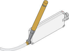
Use this procedure when connecting a cable, adapter, or some other device directly to the RF connector on the module's remote head.
The N1045A/B comes with either two 1.85 mm remote sampling heads (options 02M or 02F) or four 1.85 mm remote heads (options 04M or 04F). Option 02M and 04M connections are male center contacts and female outside threads. Option 02F and 04F connections are female center contacts and male outside threads.
- Work at a static-safe workstation.
- Visually inspect the connectors. If necessary, clean the connectors. Carefully align the connectors. The male connector center pin must slip concentrically into the contact fingers of the female connector.
- Push the connectors straight together.
- Using a torque wrench, make the final connection between the connectors while observing the following cautions. Using the torque wrench guarantees that a connection is not too tight, thus preventing possible connector damage. It also guarantees that all connections are consistently tight each time a connection is made.
Do not twist one connector into the other (like inserting a light bulb). This happens if you turn the device body rather than the connector nut. Major damage to the center conductor can occur if the device body is twisted.
Do not tighten this connection. At this point all you want is a connection in which the outer conductors make gentle contact at all points on both mating surfaces. Very light finger pressure (no more than 2 inch-pounds of torque) is enough.
This maximum torque setting is 5 in-lb (0.57 Nm) for 1.85 mm connectors.
Rotate only the connector nut when you make the connection. Do not rotate the cable or adapter.
Hold the torque wrench lightly at the end of the handle.
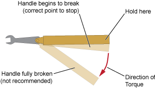
Apply force perpendicular to the wrench handle. This applies torque to the connection through the wrench. Do not hold the wrench so tightly that you push the handle straight down along its length rather than pivoting it, otherwise you apply an unlimited amount of torque.
Tighten the connection just to the torque wrench "break" point as shown in the above figure. Do not tighten the connection further.
To make a indirect RF connection to a remote sampling head connector
Use this procedure when you are connecting a cable, adapter, or some other device to a device that has already been connected to the RF connector on the module's remote head. To connect an adapter cable directly to the remote head's RF connector, use the above procedure, To make an RF connection directly to a remote sampling head connector.
- Work at a static-safe workstation.
- Visually inspect the connectors. If necessary, clean the connectors. Carefully align the connectors. The male connector center pin must slip concentrically into the contact fingers of the female connector.
- Push the connectors straight together.
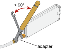
- Use an open-end wrench and a torque wrench to make the final connection between the connectors while observing the following cautions. The open-end wrench prevents any torque from being applied to the module's remote head connector. The torque wrench guarantees that a connection is not too tight, thus preventing possible connector damage. It also guarantees that all connections are consistently tight each time a connection is made.
Do not twist one connector into the other (like inserting a light bulb). This happens if you turn the device body rather than the connector nut. Major damage to the center conductor can occur if the device body is twisted.
Do not tighten this connection. At this point all you want is a connection in which the outer conductors make gentle contact at all points on both mating surfaces. Very light finger pressure (no more than 2 inch-pounds of torque) is enough.
Relieve any side pressure on the connection from long or heavy devices or cables. This will assure consistent torque when making the final connection.
Use your companies recommended torque setting for the type of adapter that you are using. (See general maximum torque setting guideline for adapter types)
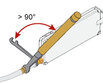
Position both wrenches within 90 degrees of each other before applying force. Wrenches opposing each other more than 90 degrees will cause a lifting action, which can misalign and damage the connection.
Rotate only the connector nut when you make the connection. Use the open-end wrench to prevent any torque from being transferred to the module's remote sampling head connector.
Hold the torque wrench lightly, at the end of the handle.
Apply force perpendicular to the wrench handle. This applies torque to the connection through the wrench. Do not hold the wrench so tightly that you push the handle straight down along its length rather than pivoting it, otherwise you apply an unlimited amount of torque.
Tighten the connection just to the torque wrench "break" point as shown in the above figure. Do not tighten the connection further.
You don't have to "fully break" the handle of the torque wrench to reach the specified torque; doing so can cause the handle to kick back and loosen the connection. Any give at all in the handle is sufficient torque.
Do not pivot the wrench handle on your thumb or other fingers, otherwise you will apply an unknown amount of torque to the connection when the wrench does reach its "break" point.
Do not twist the head of the wrench relative to the outer conductor mating plane. If you do, this will apply more than the recommended torque.
To Deskew the Remote Sampling Heads
The following deskews are available:
- Skew calibration in the Calibration dialog box which removes any difference in the electrical lengths between the two remote sampling head cables.
- Auto Deskew located in the Differential Advanced Setup dialog which quickly deskews a differential signal for skew introduced by fixtures, the device-under-test and the source.
- Hardware Skew in the Advanced Setup dialog box which manually enters horizontal skew for an individual channel.
Changing the N1045A/B's bandwidth after performing any of the above three deskews degrades the applied deskew. If you need to change the module's BW while observing the DUT, use an Instrument Setup:
- Connect the remote heads to the DUT.
- For each BW setting:
- Select the module's BW setting.
- Perform the Auto Deskew.
- Save the Instrument Setup. (File > Save > Instrument Setup)
- Recall the Instrument Setup for the desired measurement BW. (File > Open Instrument Setup)
Keeping Your Test Setup Organized
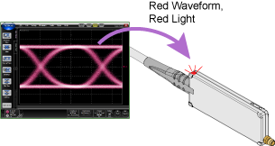
If you install four N1045A/B modules, each with four remote heads, you'll have a total of 16 channel-input cables in your test setup. To help you manage all these cables and inputs, the module comes with a channel identification head LED, cable management clips, and head clips. The color of the head LED matches the color of the associated channel waveform.
Due to the color variation in LEDs, there may be a slight color variation between the waveform and the head's light.
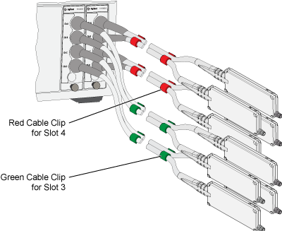
Twenty-four cable clips, six each of yellow, red, blue, and green, are provided to keep differential cables together thus reducing cable tangling. The clip's color can also be used to associate a single head or differential pair of heads with a module slot.
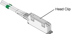
Head brackets snap over two heads to connect them together. This is especially useful when making differential measurements.
Calibration
Unlike other modules, always attach a connector saver or cable to the input connectors before calibrating an N1045A/B. Do not provide any signal. Because each remote head's sampler is located near the input connector, this technique improves calibration accuracy by increasing thermal stability and by eliminating sampler reflections as explained in the following text. The mass of the cable or connector saver affects the sampler thermal equalibrium of your test setup. Even small temperature changes during calibration can affect sampler bias levels which in turn affect bandwidth and amplitude accuracy. Every time a sampler fires, it sends a small amount of energy toward the remote head's input connector. This is normal and common in all instruments that employ a sampler directly connected to the input. Without a connector saver or cable connected, this energy reflects back so quickly that it affects the sampled calibration value. Any cable ≥1 inch (2.54 cm) long or even a connector saver, sufficiently extends the round trip time to eliminate this issue. It is not necessary to terminate the far end of the cable or connector saver.
In the module calibration dialog, a positive ΔT value indicates how many degrees warmer the current mainframe temperature is compared to the temperature of the mainframe at the time of the last module calibration. For N1045A/B modules, a positive ΔT value indicates how many degrees warmer the current remote head temperature is compared to the temperature of the remote head at the time of the last module calibration.
Monitoring a Head's Thermal Equilibrium
To monitor the thermal equilibrium of a remote head:
- Click Tools > Calibrations on FLexDCA's menu to open the Calibrations dialog.
- Click the N1045A/B tab.
- Click the Details button for the remote head's channel. This views the following Vertical Calibration Details:
- Temperature change in °C for the remote head since the last calibration.
- "The temperature has changed by more than 5.00°C" is displayed if module needs to be calibrated.
Wait one minute then open the All Calibrations dialog again. If the temperature changes more than 0.5°C, the channel is not at thermal equilibrium.
To monitor the remote head's change in temperature using remotely, use the :CALibrate:CHANnel:STATus:DTEMperature? query. You can also locate the command in the Interactive SCPI Command Tree and click the Query button.
For very high speed signals (for example, 10 ps edges), if thermal equilibrium has not been reached, the rising and falling edges will appear to move on the horizontal axis of the display screen. If during the one minute of elapsed observation time the remote head is not moved, but the displayed signal shifts to the left or right, the channel is not thermally stable. The remote head cable should be mechanically stabilized during this observation, otherwise the displayed signal may show some movement due to slight phase changes in the cable.
Stabilizing the Temperature
Each remote head represents a relatively small thermal mass and meets specifications over a ±5°C range from the last calibration temperature, measured by the internal temperature sensor and reported in the All Calibrations dialog. Factors other than the ambient air temperature will affect the operating temperature of the remote head. These factors include air currents and the temperature and thermal mass of objects in contact with the remote head. You must ensure the temperature of the N1045A/B module is stabilized prior to calibrating the module and making measurements. As with all plug-in modules, the temperature is stabilized after 1 hour of continuous operation. The preferred method to stabilize the temperature of the N1045A/B is to set up the module and remote heads in the configuration or fixture that will be used to make measurements. This includes connecting the device under test (DUT) to the remote heads.
When the internal temperature is stabilized, disconnect the DUT and perform a module calibration. If you move the remote head to a location that is thermally different than the location in which it was stabilized, you will have to wait for the temperature to stabilize again, and then calibrate the module before making measurements. For example, if the remote head is placed on a workbench for an hour, and then mounted on a cool metal fixture to make measurements, the temperature of the sampling head will begin to drop, possibly out of the ±5°C range.
The temperature, thermal mass, and thermal conductivity of the DUT will affect the internal temperature of the remote head. A DUT that is significantly different in temperature than the remote head will add thermal mass, which may increase or decrease the temperature stabilization time.
Recommendations
- Ensure that the remote head's entire surface is never outside a 15°C to 35°C temperature range.
- Verify temperatures using a thermometer. The hottest locations are likely close to the input connector and the center of the head's sides.
- If possible, leave an air gap between remote heads.
- Use forced airflow.
- When designing a cooling system, anticipate that each remote head can generate between 1 and 3 Watts of heat.
- Although the module's remote-head cable can sustain at least a 100 °C surface temperature, the cable's color might degrade if exposed to high temperatures for long periods of time. This does not damage the cable.
Secure the Remote Heads
To prevent the mass of the cable from pulling the remote head off a benchtop or out of a test fixture, five threaded mounting holes are provided as shown in the following picture. The five holes use M3 x 0.5 mm threads. Using these holes, you can attach the head to your own custom fixture. Or you can use an accessory universal bracket (N1027A-1PB) to attach the head to a probe positioner. It is important to consider the thermal properties of the remote head when designing a fixture. Larger fixtures increase the thermal mass of the remote head, which increases the time the remote head takes to reach thermal equilibrium.
The nominal length of the remote head cables is 1270 mm as measured from the module's front panel to the remote head's casing.
The maximum torque for the mounting screws is 9 lb-in.
Figure. Dimensions for Mounting Holes and Screws
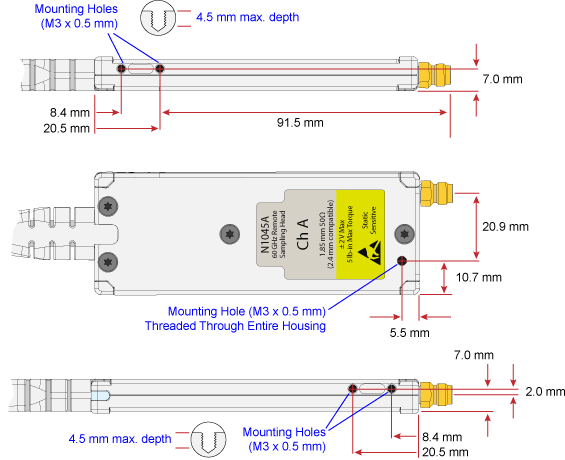
Figure. Dimensions of Head Protrusions
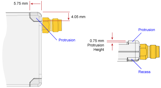
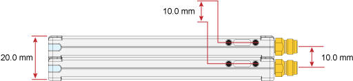
Figure. Dimensions for Two Heads Joined Together
Stability of the Remote Head Cables during Measurements
The remote head cable carries the high frequency content of the timebase signal. Changes to the physical shape of the cable (for example, bending or twisting) may horizontally skew the signal on the display screen. Changes in the shape of the cable cause variations in the effective electrical length of the cable, which translates directly to horizontal timing variations. This is important to be aware of when making jitter measurements. Vibration is similar to cable movement. Vibrating the cable may also horizontally skew the signal on the display screen. Temperature changes can also result in timing variations by adding femto or even pico seconds of change in electrical length. This electrical length change is due to the thermal expansion and contraction of the remote head cable. Use tape, cable ties, and the provided cable clips to stabilize the cables to minimize the affects of phase shift.
As with all microwave connectors, take extreme care to protect the 1.85 mm input connector. Torque forces in excess of 8 lb-in (90 N-cm) and any shear or axial forces on the 1.85 mm input connector must be avoided. Use Keysight torque wrench part number 8710-1582. Always use two wrenches when connecting or disconnecting cables or devices from the 1.85 mm connector. Use one wrench on the 1.85 mm connector of the remote head, and the other wrench on the cable (adapter, attenuator, or DUT) attached to connector. If you over-torque the RF connector, the connector may unscrew from the remote head. This will require service. If a connector loosens from the remote head, contact an Keysight service center for repair.
Supplied Accessories
| Description | Quantity |
|---|---|
| Module configuration card. | 1 |
| 1.85 mm protective cap for 02F and 02M options | 2 |
| 1.85 mm protective cap for 04F and 04M options | 4 |
| Cable management clips. One each yellow, green, blue, red. | 4 |
| Head clip | 2 |
In the following tables, the terms (m) and (f) indicate the type of center contact, male or female respectively.
1.85 mm and 2.4 mm connectors are mechanically compatible.
Options
| Option | Description |
|---|---|
| N1045-02M | 2 Channel Remote Head with 1.85 mm (m) connectors. |
| N1045-02F | 2 Channel Remote Head with 1.85 mm (f) connectors. |
| N1045-04M | 4 Channel Remote Head with 1.85 mm (m) connectors. |
| N1045-04F | 4 Channel Remote Head with 1.85 mm (f) connectors. |
Available Accessories Specific to the N1045A/B Module
| Description | Item |
|---|---|
| Replacement cable management clips. Quantity 24, six each yellow, green, blue, and red. | N1027A-1CL |
| Replacement head clip. Quantity 1. | N1027A-2CL |
| Universal probe-head-to-probe-positioner bracket. The bracket is designed to fit over 1/4-inch diameter dowel on probe positioner. | N1027A-1PB |
| Protective cap for 1.85 mm female connector | N1027A-1CF |
| Protective cap, 1.85 mm male connector | N1027A-1CM |
| Adapter, 1.85 mm (f-f) | N1027A-1FF |
| Adapter, 1.85 mm (m-f) | N1027A-1MF |
| Adapter, 1.85 mm (m-m) | N1027A-1MM |
| Adapter, 2.4 mm (m) to 3.5 mm (m) | N1027A-23A |
| Adapter, 2.4 mm (f) to 3.5 mm (f) | N1027A-23B |
| Adapter, 2.4 mm (m) to 3.5 mm (f) | N1027A-23C |
| Adapter, 2.4 mm (f) to 3.5 mm (m) | N1027A-23D |
| 2.4 mm DC block, 16V, 50 kHz to 50 GHz | N1027A-2DC |
| Accessory case | N1027A-1AC |
| Module storage case | N1027A-1MC |