N1060A Precision Waveform Analyzer Module

The N1060A Precision Waveform Analyzer module is a dual-channel electrical module with integrated, compliant clock recovery, and a built-in precision time base. This is a three-slot wide module. When installed in an 86100D, waveform acquisition time is increased.
For optimum performance, the N1000A should be used with the following options. Without these options, the features provided with the N1060A module will be reduced.
- Low-jitter timebase (N1000A-LOJ),
- Pattern Lock Capability (N1000A-PLK, 86100D-ETR), and
- Enhanced Jitter Analysis feature (N1000A Research and Development Package).
An N1060A with a serial number ≥ MY62100101 or ≥ US62100101 requires FlexDCA firmware version A.06.90 or later.
For N1060A modules with a serial number < MY62100101 or < US62100101 The minimum required firmware version is A.06.00 (FlexDCA) for both the N1000A and 86100D.
Maximum electrical signal input for N1060A modules is ±1Vpp single-ended. Damage will occur at input powers above this level.
The maximum torque setting is 3 in-lb (0.34 Nm) for 1.0 mm connectors and 8 in-lb (0.9 Nm) for 2.92 mm standard connectors.
To deskew the channel inputs, use external phase trimmers.
Automatic Relock
If the clock recovery module loses lock, the trigger becomes asynchronous with the data and the instrument will not display a correctly triggered waveform. By default, when lock is lost, the instrument automatically tries to re-establish lock. Automatic relocking is most helpful when probing a device under test. You can turn off or on automatic relocking from the Clock Recovery setup dialog. Loss of lock, or false lock, conditions may be caused by unusual patterns with a large amount of consecutive 1's or 0's. If the module loses lock during any procedure or measurement, reestablish lock and then repeat the procedure or measurement. For example, if lock is lost while saving a pattern waveform to a file, the data stored in the file will be corrupt.
Locking on the Data Rate
When using the module, you must specify the symbol rate of the clock to be recovered and lock the module on the symbol rate. Under two conditions, the module may lock on a symbol rate other than the specified rate. In the first condition, lock can occur if the entered symbol rate is an integer multiple of the actual symbol rate of the signal. The second condition occurs because the acquisition range is broad (greater than ±5000 PPM). This makes it possible for the module to lock on a signal that is higher or lower than the selected value. For example, if you select a 2.48832 GBd symbol rate but the signal is actually 2.5 GBd, the module may still lock on the signal.
Option IRC
Option IRC provides optical channel System Impulse Response Correction (SIRC) measurement and data files. These files provide an ideal channel response. SIRC data can be applied in the System Impulse Response Correction dialog. The SIRC correction data feature is a digital filter that is used to:
- Improve the response of module reference filters to more closely match an ideal receiver.
- Enable non-standard reference receiver rates or bandwidths.
- Increase the bandwidth of the channel by up to 50%.
- Ensures that an eye diagram will look identical between different modules.
SIRC correction data is unique to a specific module (serial number). Option IRC ships standard with every module and does not need to be purchased.
| Module/Option | Channel | Range1 Min SIRC Freq. |
Range1 Max SIRC Freq. |
|---|---|---|---|
| N1060A Option 050 | All | 25 GHz | 60 GHz |
| N1060A Option 085 | All | 25 GHz | 100 GHz |
| N1060A Option E33, 050 | All | 16.5 GHz | 60 GHz |
| N1060A Option E33, 085 | All | 16.5 GHz | 100 GHz |
Only available with option IRC and compliance not guaranteed.
Loop Bandwidth and Jitter
When measuring jitter relative to the recovered clock, jitter that is present on both the data and the recovered clock can not be detected by the instrument. Jitter that is within the clock recovery module's loop bandwidth appears on the recovered clock. Jitter that is outside of the loop bandwidth does not appear on the recovered clock and can be detected on the data.
Specific jitter frequencies in the vicinity of the loop bandwidth may appear amplified or attenuated due to the scope timebase delay and clock recovery group delay. The electrical through-path does not have a delay line. Compensation can be made, by adding an electrical cable between the electrical output and the vertical channel. However, this may affect signal quality.
If the display shows a clock recovery lock lost status message, clock recovery cannot be established on the signal. Make sure that your signal is attached with a power level greater than the minimum (see the specifications) and that the symbol rate is set correctly to within the specified acquisition range.
To use the front-panel clock above 3.2 GBd, Keysight N1060A modules require an instrument with the enhanced trigger option. Or, the front panel output divide ratio must be set on the N1060A to reduce the frequency below 3.2 GHz.
Available Options
| Item | Description |
|---|---|
| Bandwidth Options | |
| N1060A–50 | 50 GHz BW. Two channel electrical, 2.4 mm (f) connectors. |
| N1060A–85 | 50 GHz, 70 GHz, and 85 GHz BW plus 95 GHz BW (characteristic). Two channel electrical, 1.0 mm (f) connectors. |
| Clock Recovery Options | |
| N1060A–216 | Clock recovery input symbol rate range of 125 MBd to 16 GBd (continuous). |
| N1060A–232 | Clock recovery input symbol rate range of 125 MBd to 32 GBd (continuous). |
| N1060A–264 | Clock recovery input symbol rate range of 125 MBd to 64 GBd (continuous). |
| Advanced Features | |
| N1060A–EVA | Integrated, variable equalizer. |
| N1060A–JSA | Jitter Spectrum Analysis and Clock Recovery Emulation. |
| Precision Timebase Options | |
| N1060A–PTB | Precision Timebase, ultra-low random jitter. This option is automatically included with every N1060A module. |
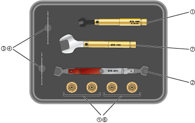
N1060A Accessory Kit
The N1060A accessory kit includes the required torque wrenches, open-end wrenches, and adapters to make connections to the N1060A’s front-panel RF connectors. To prevent expensive repairs and repair downtime, take a few minutes to study the information in the following pages.
| Item | Description | Qty | Part Number |
|---|---|---|---|
| 1 | Torque wrench, 5/16-in open end, 5 lb-in (0.57 Nm) | 1 | 8710-1582 |
| 2 | Dual Torque wrench, 14 mm open end, 4 lb-in (0.45 Nm) and 10 lb-in (1.13 Nm) |
1 | 8710-2819 |
| 3 | Open end wrench, 8 mm | 1 | N1060-20009 |
| 4 | Open end wrench, 7 mm | 1 | 8710-1761 |
| 5 | Channel Input adapter, 1 mm (f) to 1.85 mm (f) | 2 | Y1901B (5067-1392) |
| 6 | Channel Input adapter, 1 mm (f) to 2.92 mm (f) | 2 | Y1903B (5067-1393) |
| 7 | Torque wrench, 20 mm open end, 8 lb-in (0.9 Nm) | 1 | 8710-1764 |
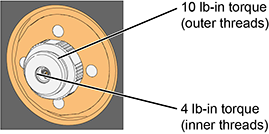
Channel Input Connectors
On several DCA-X modules and DCA-M modules, a front-panel 1 mm Channel Input connector is used as shown in this picture. These 1 mm connectors have both outer in inner threads that require different torque specifications. Always use the correct torque specification as noted when making connection to the Channel Input. Damage to the Channel Input connector results in an expensive repair and extended down time while the module is being repaired.
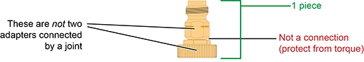
Channel Input Y1901/3B Adapters
The following picture show the two types of ruggedized 1mm adapters, which are supplied in the N1030A and N1060A accessory kits:
- 1 mm to 1.85 mm Y1901B adapter
- 1 mm to 2.92 mm Y1903B adapter
These adapters are designed to be installed on the front-panel channel inputs. It is recommended that you always use them. Due to the physical requirements needed to obtain high performance, the geometry of these, as well as all, 1 mm connectors, demands special care to avoid expensive damage as explained in this document.
Making RF Connections
- Work at a static-safe workstation.
- Visually inspect the connectors. If necessary, clean the connectors. Carefully align the connectors. The male connector center pin must slip concentrically into the contact fingers of the female connector.
- Push the connectors straight together.
- Tighten lightly using only your fingers as, at this point, all you want is a connection in which the outer conductors make gentle contact at all points on both mating surfaces. Very light finger pressure (no more than 2 pound-inches of torque) is enough.
Do not twist one connector into the other (like inserting a light bulb). This happens if you turn the device body rather than the connector nut. Major damage to the center conductor can occur if the device body is twisted.
- Use a torque wrench to make the final connection. This guarantees perfectly tight, consistent connections that prevents connector damage. Refer to Applying Torque for the proper handling of the wrenches and to view the correct connector “flats” on which to position the wrenches.
The maximum torque setting is 4 in-lb (0.45 Nm) for 1.0 mm connectors.
Rotate only the connector nut when you make the connection. Do not rotate the cable or adapter.
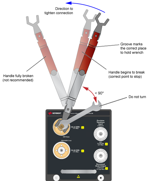
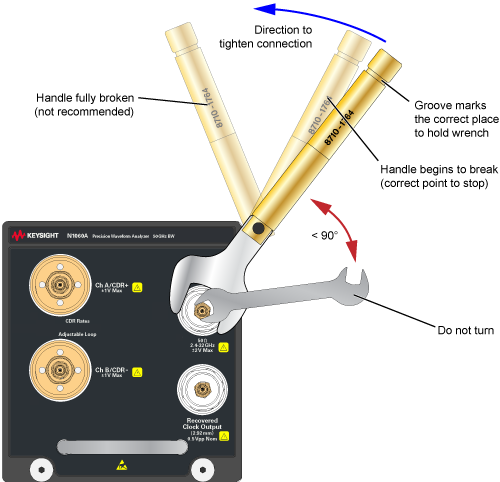
Hold the torque wrench lightly at the groove located at the end of the handle.
Apply force perpendicular to the wrench handle. This applies torque to the connection through the wrench. Do not hold the wrench so tightly that you push the handle straight down along its length rather than pivoting it, otherwise you apply an unlimited amount of torque.
Tighten the connection just to the torque wrench "break" point as shown in Wrenches Positioned on Correct Flats. Do not tighten the connection further.
Applying Torque
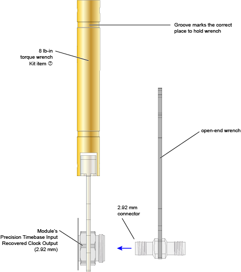
For the 1 mm Channel Input connector, use the dual torque wrench shown in the Wrenches on Channel Input. For the N1060A’s front-panel Precision Timebase and Recovered Clock 2.92 mm connectors use the 8 lb-in torque wrench as shown in Wrenches on Precision Timebase Input (or Recovered Clock Output).
The silver end of the dual torque wrench is 4 lb-in. The red end of the torque wrench is 10 lb-in.
For the 2.92 mm Precision Timebase and Recovered Clock connector, use 8 lb-in torque wrench shown in the Wrenches on Precision Timebase Input (or Recovered Clock Output).
Selecting and Positioning the Wrenches
The following figures show the proper “flats” on which to place the wrenches for several possible connections.
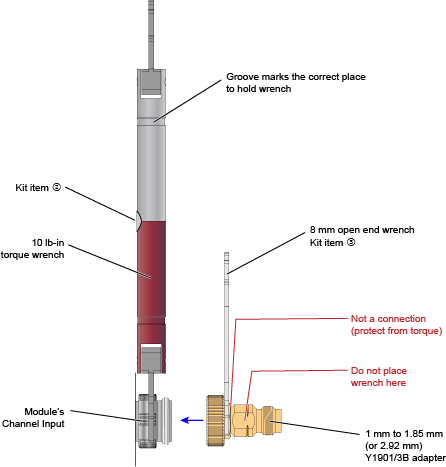
Y1901/3B Adapter to Channel Input
This figure show the correct placement of the 10 lb-in dual torque wrench (the red end) and the 8 mm open end wrench. On the Y1901/3B adapter, connect the 8 mm wrench on the flats that are adjacent to the knurled ring as shown in this figure.
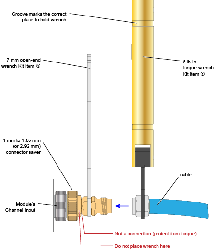
Cable or Adapter to Y1901/3B Adapter
This figure show the correct placement of the 5 lb-in torque wrench and the 7 mm open end wrench for connecting a cable, adapter, or other item to the Y1901/3B adapter.
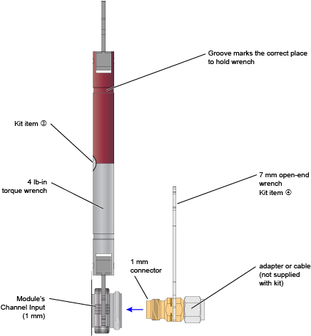
Adapter to Channel Input (without Y1901/3B)
It is recommended that you always connect an Y1901/3B adapter to the 1mm channel input. However, if you want to connect an adapter or cable directly to a channel input connector, use the 4 lb-in end of the dual torque wrench (silver end of the dual torque wrench). Do not use the red end of the dual torque wrench which is only used when connecting the stronger outside channel-input connector threads to the Y1901/3B connector.
Never apply in excess of 4 lb-in of torque to the 1mm channel input’s inner threads. Confirm also that your adapter or channel connector can withstand 4 lb-in.
Adapter to 2.92 mm Connectors
This picture shows connecting a 2.92 mm-to-2.92 mm adapter to either an N1060A's front-panel Recovered Clock output or Precision Timebase input. Both of these connectors are 2.92 mm.