N1022A/B Active Probe Adapter
The N1022B and N1022A Active Probe Adapter allows you to connect active probes that use the Infiniium AutoProbe Interface to an electrical channel. After connecting the probe, the instrument automatically detects the connection and prompts you to select the probe's model number from a list. The vertical offset control located on the front panel of many plug-in modules can be used to adjust probe offset.
There are a few things to consider when connecting the N1022A/B Active Probe Adapter to an active probe and the DCA.
- The dynamic range of the system will be 3.2V (6.4Vp-p), which, with probe offset, covers most digital technologies.
- The DCA provides both power and offset control to the active probe adapter through the plug-in module front-panel connector.
- Probe offset is changed by adjusting the vertical offset control located on the plug-in module front panel. The control should be adjusted to center the signal within the 5V peak-to-peak (12 volts peak-to-peak for slow signals) dynamic range of the probe.
Electrical channel input circuits can be damaged by electrostatic discharge (ESD). Therefore, avoid applying static discharges to the front panel input connectors. Avoid touching the front-panel input connectors without first touching the frame of the instrument. Be sure that the instrument is properly earth-grounded to prevent buildup of static charge. Wear a wrist-strap or heel-strap.
Channels with 2.4 mm Electrical Input
The N1022A/B can be directly connected to any 86100-series or 83480-series module with a 3.5 mm electrical channel input. You can also connect the probe adapter to a module with 2.4 mm electrical input. However, in order to connect to a 2.4 mm input, you must use a 2.4 mm (F) to 3.5 mm (M) adapter, Keysight part number 85130-60010.
Supported Probes
- N2750/1/2A Differential probe. 2:1 differential mode only.
- 1131A 3.5 GHz InfiniiMax active probe
- 1132A 5 GHz InfiniiMax active probe
- 1134A 7 GHz InfiniiMax active probe
- 1168A 10 GHz InfiniiMax active probe
- 1169A 12 GHz InfiniiMax active probe
- 1152A 2.5 GHz Active Probe
- 1156A 1.5 GHz active probe
- 1157A 2.5 GHz active probe
- 1158A 4 GHz active probe
Available Accessory
8 in-lbs torque wrench: Keysight part number 8710-1764
Procedure
- Connect the N1022A/B probe adapter to the electrical input of the module. This requires holding the N1022A/B's connector steady while turning the module's input connector. This action threads the module's connector into the N1022A/B's connector. Torque the connection to 8 in-lbs. An 8 in-lbs torque wrench is available from Keysight. Order part number 8710-1764.
- Connect the probe output to the probe adapter input. The probe tip should not be connected to a device under test at this time.
- Connect the probe adapter's power connector to the module's front-panel Probe Power connector for the associated channel. Do not make the connection to any Aux Power connector, if one is present on the module's front panel. Connecting to an Aux Power connector prevents the probe from being automatically calibrated.
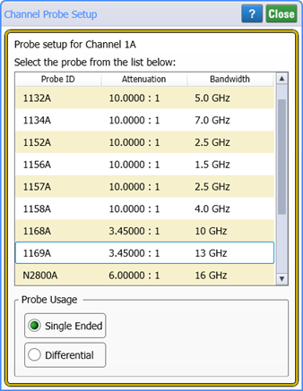
- The N1000A's Probe Channel dialog automatically opens.
- Select the probe model that is currently connected to the probe adapter. If you are using a probe that is not listed in the supported probe list, select one of the probes from the supported list that is closest in type to your unspecified probe.
- Click Close. You can now change the probe tips or probe attenuation. You can also perform a probe calibration.
- Perform the probe calibration procedure so that the DC gain, offset zero, and offset gain will be calibrated.
To ensure good connections and to avoid damaging the connectors, tighten the connection to 8 in-lbs of torque. After the adapter is connected, do not allow the adapter to rotate on the front-panel connection.
The probe power cable connector automatically locks in the mating power connector. To separate the connection, you must pull on the knurled part of the cable connector housing. This releases the lock. If you pull directly on the power cable, the connectors will not release and may damage the connector or cable. An effort has been made to design this active probe adapter to take more than the average amount of physical and electrical stress. However, the technologies necessary to achieve high performance do not allow the probe to be unbreakable. Treat the probe adapter with a moderate amount of care.