Probe Types
There is no such thing as the perfect probe, so you must use some discretion in choosing the best type of probe for each measurement. To make the correct choice, it's helpful to know the equivalent circuit of the circuit under test. Some knowledge of the expected signal, particularly its rise time or spectral content, is useful in making a probe choice. It is also important to know what parameter (voltage or time) you need to measure most accurately, because some trade-off may be required in the measurement. There are two common types of probes suitable for use with the instrument: active and resistive divider (passive). Each type has different loading effects. The resistive divider probe is for 50Ω inputs.
Active Probes
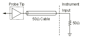
An active probe has a buffer amplifier at the tip, as shown in the following graphic.

This buffer amplifier drives a 50Ω cable terminated in 50Ω at the analyzer input. Active probes offer the best overall combination of resistive loading, capacitive loading, and bandwidth. The disadvantages of active probes include the larger size of the tip and a somewhat limited input dynamic range.
Resistive Divider Probes (Passive Probes)
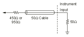
Resistive divider (passive) probes are designed for instruments with a 50Ω input impedance. The tip of the probe has a series resistor. The cable is designed for a 50Ω transmission line. Because the cable is terminated in 50Ω at the analyzer input, it looks like a purely resistive 50Ω load when viewed from the tip. Therefore, the resistive divider is flat over a wide range of frequencies, limited primarily by the parasitic capacitance and inductance of the resistor and the fixture that holds it. The input resistance of the probe to the circuit under test is either 500Ω or 1 kΩ.

Due to the following two factors, the resistive divider probe has the lowest capacitive loading of any probe:
- the divider's physical geometry
- the divider does not have to be compensated by capacitance
This low capacitance and its inherent wide bandwidth make it best suited for wide bandwidth measurements or those measurements where timing is the most critical parameter. The disadvantage of this type of probe is its relatively heavy resistive loading. Not all circuits can drive 500Ω or 1 kΩ. Even for measurements in a relatively low impedance circuit, the amplitude errors can be significant. Changes in bias levels or operating current in the circuit under test might affect the circuit's behavior.